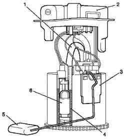
Fig. 3.2. The flow of hydraulic clutch: 1 - Adapter 2 - a special tool MKM-6174-2, 3 - a special tool MKM6174-1, 4 - valve pumping
Remove the valve cap from the valve pumping and attach a special tool MKM-6174-1 to the valve pumping (Fig. 3.2). Remove air from the clutch. Turn on the device for removing air from the hydraulic drive. Open the valve pumping (2-3 overleaf). Pump to release the brake fluid without bubbles. Close (by hand) valve pumping. Removing device Unplug the device for removing air from the hydraulic drive. Disconnect the adapter device for removing air from the hydraulic drive. NOTICE Must take the following steps to fill the discharge line transmission housing of the working cylinder clutch. When pumping, make sure the tank is filled with hydraulic brake system. Remove air from the discharge line of the working cylinder clutch. Install special tool MKM-6174-2 at MKM-6174-1 on the valve pumping, lower the free end in a suitable container Press and hold the clutch pedal. Open the valve pumping. Open the valve before pumping air and / or a mixture of air / brake fluid. Close (by hand) valve pumping. Slowly release the clutch pedal and wait approximately 5 seconds. Repeat the procedure four times. Tighten the valve point pumping 5 Nm Remove the special tools MKM-6174-1, and MKM-6174-2. Remove the cap from the valve pumping. Fill the tank hydraulic clutch brake fluid to the mark «MAX». Close the tank hydraulic brake system. Check the opening pressure of the clutch pedal. Check to include all gear with the engine running and clutch depressed. NOTE Take a test drive to ensure precise work the clutch and braking. The trip was spend with different speeds and frequent gear changes to achieve operating temperatures.
Removal, inspection and installation of hard plates and the driven clutch plate (without SAC) NOTE To prevent damage to the petals spring thrust plate use a special device KM-6263 after removal and installation.
326