2 minute read
Checking the tension of the toothed belt (engine 2.0 l


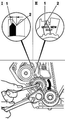
Fig. 2.73. Re-adjust the tension on
the toothed belt tension pulley index: 1 - pointer tension pulley, 2 Tag
Option II: Index tension pulley toothed belt combined to tag «USED» (Figure 2.73). Tighten the attachment bolt tension pulley toothed belt moment 20 Nm Remove the device KM 853
Check after adjustment
Rotate the crankshaft by two turns (720 °) in the direction of rotation of the engine in TDC position of the first cylinder and check the adjustment of tension pulley toothed belt. If the pointer tension pulley toothed belt is not combined with the label, repeat the process of adjustment.
NOTE This operation applies only to the toothed belt after running. When installing a new toothed belt must be adjusted. The test is performed on the engine is cold - at room temperature.
Removing components
Disconnect the mass wire from the battery Remove the air filter housing with the sensor mass air flow. Simply unplug the wiring harness connector sensor mass air flow. Relaxed the collar and unscrewing bolts, disconnect the air intake hose inlet pipe. Loosen the mounting bolts and remove the upper lid toothed belt with a toothed belt rear cover Check direction of rotation of Poly-V belt.
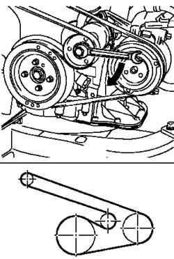
Turn Poly-V belt tensioner in the direction of the arrows in Figure 2.74. Clear Poly-V belt Remove the lower engine splash guard. Turn Poly-V belt tensioner (clockwise) and block, using a suitable mandrel.
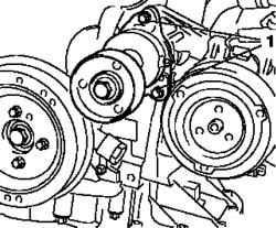
Fig. 2.75. Screw tensioner Poly-V
belt: 1 - screws
Loosen the clamping screws and remove the bearing compressor tensioner Poly-V belt (Figure 2.75). Remove the snubber, holding his attachment bolt drive gears.
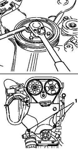
Remove the mounting bolts and detach the bottom of the cover toothed belt from the back of the cover toothed belt (Figure 2.76). Rotate the crankshaft in the position of top dead center (TDC) of cylinder number 1 (ignition) in the direction of rotation of the engine (tag 2) Turn the screw for mounting drive gears.
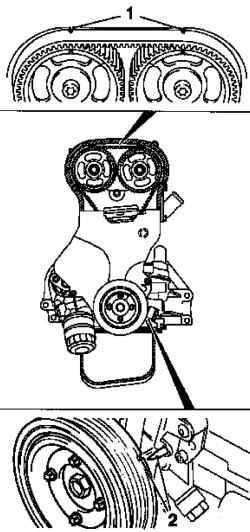
Fig. 2.77. Install the crankshaft
position at top dead center (TDC) of cylinder number 1: 1 - marks on the lid of the cylinder head, 2 - a label at the crankshaft
Notches on the camshaft sprocket should be aligned with marks on the lid of the cylinder head (Figure 2.77).
NOTE Locking device KM-853 should be installed in this position.
Adjust the synchronization of the timing mechanism in case of need.
Test
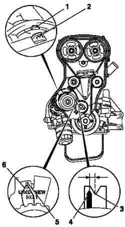
Fig. 2.78. Check the installation of


