5 minute read
The principle of controlled camshaft sprockets


Running the engine at idle
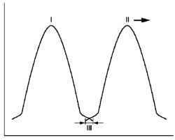
Fig. 2.5. Diagram of the engine
during the idling: I - intake valve lift; II - rise of the exhaust valve, ahead; III - minimal overlap of valves
Idle set minimum valve overlap, since a high value of the vacuum in the inlet pipe allows a large number of residual gas to fall back into the cylinders, even with a slight overlap. This ensures uniform operation of the engine at idle.
Running the engine in a mode of small and medium-sized loads
While small and medium-sized loads have large valve overlap, because the engine in these conditions allows for a greater number of residual gases. The result is a substantial reduction of nitrogen oxide emissions.
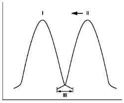
Fig. 2.6. Diagram of the engine
during operation in the mode of small and medium-sized loads: I intake valve lift; II - rise of the exhaust valve, ahead; III - minimal overlap of valves
In the upper range of the regime of partial loads, closer to full load, valve overlap is minimized, because the engine in this range require the maximum amount of fresh mixture.
Adjusting the overlap valve replaced previously used technology of exhaust gas recirculation. To achieve maximum filling of the cylinder, is also important to agree on the time of closing the intake valves with the engine speed.
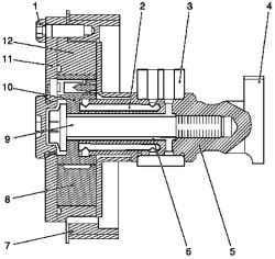
Fig. 2.7. Cross-section of oil
sending control camshaft drive intake valves: 1 - attachment bolt - a cover of the regulator of camshaft 2 - oil pipe to the chamber "A" regulator of camshaft 3 - block bearing camshaft, 4 - cams, 5 camshaft; 6 - oil feed to the cameras "B" regulator of camshaft; 7 toothed belt pulley 8 - separation chambers "A" and "B", 9 - bolts fastening the regulator of camshaft, 10 - rotor, 11 - a cover of the regulator of camshaft, 12 - Stator
Camshaft control system consists of hydraulic control, which is enshrined in the anterior part of the camshaft, a control valve mounted on the cylinder head, oil between the valve guide and camshaft position controller camshaft (holes in the camshaft), as well as electronic control circuit with feedback.
To properly adjust the camshaft must implement continuous oil flow from the periphery of the lubrication system.
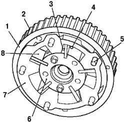
Fig. 2.8. Regulator camshaft drive
intake valves: 1 - separating disk (external) - the regulator camshaft drive intake valves, 2 - toothed belt pulley 3 - channel fill and drain - the camera "A" 4 - channel fill and drain - the camera "B"; 5 - screw pin - Lid regulator of camshaft 6 - rotor is rigidly connected to the camshaft; 7 - stator can be moved hydraulically, 8 - separation chambers "A" and "B"
Motor oil is fed through a special oil line from oil pump to the cylinder head and block camshaft bearings. Camshaft bearing block contains a solenoid valve for each of the controlled camshaft; this valve delivers oil in the oil line of the control camshaft position to fill or drain the camera «A» or «B» the regulator of camshaft or maintain the current installation of camshaft.
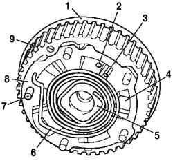
Fig. 2.9. The regulator exhaust
valve camshaft drive: 1 - separating disk (internal) - the regulator camshaft drive intake valves, 2 channel fill and drain - the camera «A»; 3 - channel fill and drain - the camera «B»; 4 - separation chambers «A "and« B »; 5 - rotor is rigidly connected to the camshaft 6 - return spring, moves the stator to its original position in the absence of oil pressure; 7 - threaded pin Lid regulator of camshaft 8 - stator can be moved hydraulically, 9 pulley toothed belt
Oil to the appropriate chamber «B» the regulator of camshaft is served on the flange bolts. Oil to the corresponding cell «A» regulator of camshaft is served by a separate, off-center channels. Lifting height varies valve when filling or discharge of oil from the chambers of the regulator of the intake camshaft and exhaust valves.
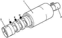
Fig. 2.10. Electrohydraulic valve: 1
- body with an electromagnet, 2 - a connection through the wiring harness connector, 3 - cross section of the valve with a groove for connecting the annular grooves I and II and the center channel for connecting the annular grooves (III) to drain the oil
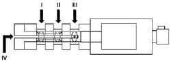
Fig. 2.11. Block diagram of the
electrohydraulic valve
Electrohydraulic valves direct the flow of engine oil to the appropriate channels to fill or drain the oil from the chambers «A» or «B». This action is the movement of the valve in one of three provisions. Valve controls the engine control module.
An annular groove II associated with the ring groove I, allowing you to switch pressurized oil feed to the camera «A» or chamber «B». An annular groove III serves only to drain the oil from the chamber IV «B».
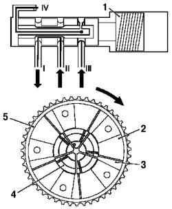
Fig. . Wiring the supply line to the oil guide chamber "A" camshaft position controller: 1 electromagnetic hydraulic valve, 2 Camera «A»; 3 - camera «B»; 4 rotor, 5 - stator
Feedline II constantly connected with a source of oil under pressure. Figure 2.12 shows the position of the valve, where the feedline is connected to the oil guide chamber "A" camshaft position controller. Luggage «B» control of both camshafts is emptied through a discharge channel III and IV.
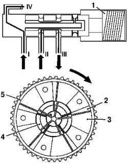
Fig. 2.13. Wiring the supply line to


