3 minute read
Checking the pressure loss in the engine (2,0 l


Installation components
Raise the car. Install the engine splash guard. Lower the car. Insert the oil dipstick hole. Replace the cover expansion tank coolant. Replace spark plugs with sptsialogo tool KM 6363 and then tighten the moment 25 Nm Fig. 2.51. Ignition Module
Replace ignition module, replacing the 4 pads (Figure 2.51). Tighten the two screws fastening point 8 Nm Install the ignition module cover. Replace the front cover of a toothed belt.
NOTICE Check that the lids.
Tighten the two screws fastening the cover time 6 Nm Replace the air filter housing, tighten the attachment bolt and attach the clamp moment 3,5 Nm Install inlet pipe. Connect the wiring harness air flow sensor. Connect the battery pack. Tighten the nut mounting terminals. Program transient memory. Close the hood.
Removing the air filter housing
Open the hood.
NOTE Before the verification procedure warming up the engine to operating temperature (oil temperature - 80 ° C).
Remove the air filter housing with the sensor mass air flow. Unplug the wiring harness connector sensor mass air flow.
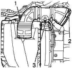
Fig. 2.52. Components, shooting
in the dismantling of the air filter: 1 attachment bolt, 2 - clamp, 3 - the wiring harness connector sensor mass air flow
Removing the intake manifold
Remove the intake manifold. Loosen the mounting bolt and remove the vent hose from the engine cylinder head cover.
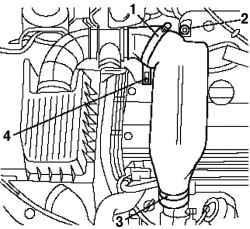
Fig. 2.53. Mounting inlet pipe: 1, 3,
4 - clamps, 2 - screw fixing
Remove the clamps and separate the inlet pipe from the turbo and remove it (Figure 2.53). Remove the air hose pressurization.
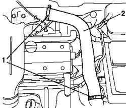
Fig. 2.54. Hose Pressurization: 1 -
clamps, 2 - Hose Pressurization
To do this, remove the two clamps and disconnect the air hose blower (Figure 2.54).
Removing the pipe deflection air pressurization
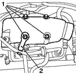
Fig. 2.55. Mounting pipe deflection
air pressurization: 1 - mounting screws, 2 - Bracket
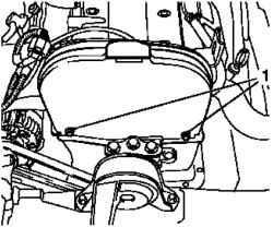
Fig. 2.56. Removing the upper part
of lid toothed belt: 1 - bolts fastening
Loosen the mounting bolts and separate the upper cap element toothed belt from the back cover (Figure 2.56).
Removing the ignition module
Disconnect the wiring harness connector from the ignition module. Remove the ignition module in the direction of the arrow shown therein.
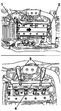
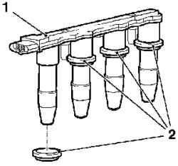
Fig. 2.57. Components shooting in
dismantling the ignition module: 1 ignition module cover, 2 - wiring harness connector ignition module, 3 - a special tool, 4 - ignition module
Loosen the mounting bolts and detach the ignition module from the spark plugs, using a special tool KM 6009 (Fig. 2.57). Remove the spark plugs, using a special tool KM-194-E. Remove the oil-filling neck. Remove the coolant expansion tank. Remove the oil dipstick.
Install the crankshaft position at top dead center (TDC), piston cylinder number 1 and the connection tester
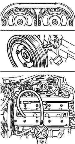
Fig. 2.58. Install the crankshaft
position at top dead center (TDC), piston cylinder number 1 and the connection tester
Rotate the crankshaft of the engine in the direction of rotation, set the piston cylinder number 1 in the position of top dead center (TDC), using the attachment bolt finger pulley belt transmission (Fig. 2.58).
NOTE At the same time slots on the camshaft sprocket should be aligned with marks on the lid of the cylinder head.
Rotate the crankshaft slowly and smoothly. Connect the tester to the system pressure drop, the compressed air. Calibrate the tester pressure drop. Replace the connection piece in the candle hole cylinder number 1 and plug the tester pressure drop to the adapter (in accordance with the manufacturer's instruction).
NOTICE During the test, the rotation of the crankshaft is not allowed. to avoid rotation, including 1-S transmission and the parking brake systems.
Determine the pressure drop in percentage terms. Listen carefully to the sound of air leakage from the intake manifold, exhaust system or crankcase and pay attention to the bubbles in the coolant expansion tank. The maximum pressure drop between the individual cylinders is approximately 10%, the maximum pressure drop in one cylinder should not exceed 25%.


