8 minute read
Removing and installing cylinder head (engine 1,4-1,6 l


Withdrawal
Open the hood
NOTE Before the verification procedure warming up the engine to operating temperature (oil temperature - 80 ° C).
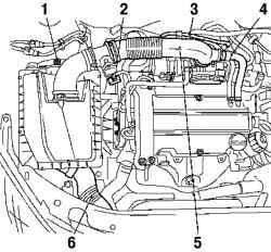
Fig. 2.212. Components, shooting
in the dismantling of the air filter: 1 screw fixing the lower rubber support, 2 - wiring harness mass air flow sensor, and 3 - line of ventilation of the fuel tank, 4 - hose, ventilation motor, 5 - air intake hose, 6 - inlet pipe
Remove the air filter housing (Fig. 2.212). Disconnect the wiring harness sensor mass air flow. Disconnect the fuel tank ventilation line. Disconnect the ventilation hose from the engine air intake hose. Removing the clamp, disconnect the hose from the air intake throttle pipe. Removing the clamp, remove the air filter housing. Loosen the screw fixing the lower rubber support and unplug it. Disconnect the inlet pipe.
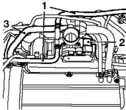
Fig. 2.213. Removal of cooling
nozzles to throttle: 1, 3 - schlangi coolant 2 - connector wiring harness throttle tube
Disconnect the wiring harness connectors throttle tube (Fig. 2.213). Disconnect the coolant hoses from the throttle tube. Place the bottom of the container for drainage. Remove the 2 clamps. Disconnect the coolant hose.
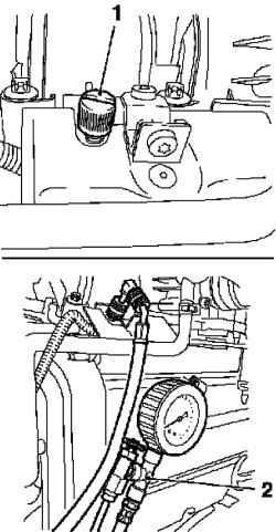
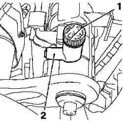
Reset the fuel pressure with a special tool KM-J-34730-91 through the test socket to loosen the protective cover of the test connections (Fig. 2.214). Collect withdrawing fuel in a suitable container. Observe safety rules and requirements of local legislation
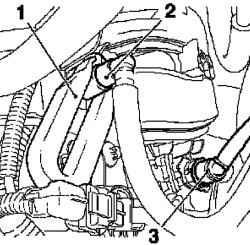
Fig. 2.215. Removing the fuel line
and vacuum line: 1 - a special tool, 2 - feeding the fuel line, 3 - vacuum brake booster line
Disconnect the fuel line feeding from the fuel rail with a special tool KM 796 (Fig. 2.215). Disconnect the quick release coupling. Disconnect the brake booster vacuum line from the intake manifold. Disconnect the quick release coupling. Disconnect the vent line from the fuel tank intake manifold. Disconnect the wiring harness connector vent the fuel tank. Disconnect the front exhaust pipe from the catalytic converter 3 unscrewing nuts. Place the bottom of the container for drainage
Attach a suitable hose to the drain fitting (2.216). Loosen the drain screw coolant. Drain the coolant. Tighten the drain screw coolant.
Disconnect power supply systems and engine control
Disconnect the wiring harness connectors engine control module. Disconnect the fuse. Disconnect the 2 wires mass by unscrewing 2 nuts. Disconnect the wiring harness plugs 6 engine: cap, ignition module, sensor oil pressure, coolant temperature sensor, camshaft sensor.
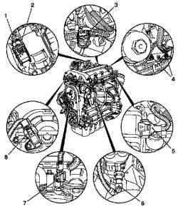
Fig. 2.217. Disconnect power
supply systems and engine control: 1 - connector wiring harness engine control module, 2 - fuse, 3 zalushka 4 - the mass of wire, 5 plug plug ignition module 6 - cap connector oil pressure sensor, 7 plug connector sensor coolant temperature, 8 - plug connector camshaft sensor
Release the wiring harness.
Remove the thermostat housing from the coolant pump, 3 unscrewing bolts.
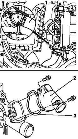
Fig. 2.218. Removing the
thermostat housing: 1 - coolant hose, 2 - body thermostat, 3 gasket
Remove the gasket.
Disconnect the coolant hose from the radiator.
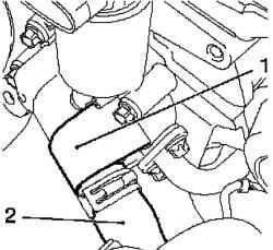
Fig. 2.219. Disabling the cooling of
the exhaust gas recirculation valve: 1 - exhaust gas recirculation valve, 2 - hose coolant
Disconnect the coolant hose from the valve exhaust gas recirculation (Fig. 2.219). Loosen the clamp. Disconnect the wiring harness of oxygen sensor. Remove the cover bracket. Disconnect the wiring harness from the bracket. Remove the engine lifting bracket by unscrewing 2 screws fastening. Loosen the heat shield. Unscrew the 2 screws. Remove the guide tube probe for measuring the oil level.
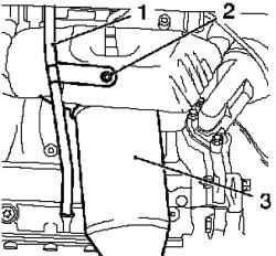
Fig. 2.220. Removing the tube
probe for measuring the oil level: 1 guide tube probe for measuring the oil level 2 - bolt krepelniya 3 - intake manifold
Disconnect the exhaust manifold.
Loosen the screw. Remove the exhaust manifold by unscrewing 9 bolts.
Removing the oil filter
Remove the lid from the oil filter housing. Remove the oil filter element. Remove the oil filter housing from the cylinder by unscrewing 3 bolts. Remove the gasket. Clear Poly-V belt. Mark direction of rotation. Turn Poly-V belt tensioner clockwise using a device KM 6131.
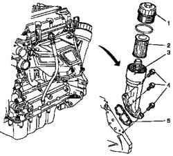
Fig. 2,221. Disconnect power
supply systems and engine control: 1 - cap 2 - filter element 3 - the oil filter housing, 4 - bolts fastening, 5 gasket
Set device KM-955-2.
Loosen the tensioner Poly-V belt. Remove the belt pulley pump coolant from the coolant pump, 3 unscrewing bolts. Remove the casing valve timing mechanism. Loosen 4 bolts mounting the pump coolant. Loosen the 5-bolt mounting Corps timing mechanism. Disconnect the sensor from camshaft timing mechanism housing by unscrewing bolts. Disconnect the ventilation hose from the cover of the engine cylinder head.
Removing the ignition module
Remove the wiring harness ignition module. Remove the ignition module with the lid of the cylinder head in the direction of the arrow Loosen the two bolts. Separate the ignition module from the spark plug with a special tool KM 6009. Remove the lid of the cylinder head from the cylinder head by unscrewing the mounting bolts 13. Remove the cap base of the cylinder block.
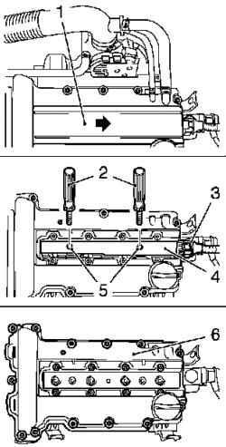
Fig. 2.222. Components shooting
in dismantling the ignition module: 1 - ignition module cover, 2 - a special tool; 3 - Ignition module wiring harness, 4 - ignition module 5 - mounting screws, 6 - cylinder head cover
Lower the car.
Install the first piston cylinder in position TDC (the ignition) Install special tool KM-952. Smoothly rotate the crankshaft until the special tool the CM 952 does not reach the stop. Check belt pulley on the crankshaft must be aligned with the projection on the case of the mechanism of timing. Remove the guide from the cylinder head by unscrewing 2 screws fastening. Remove the camshaft gears by unscrewing 2 screws fastening. Hold open spanner for hexagon camshaft. Put an asterisk camshaft on one side with a chain timing mechanism in the body.
Removing the cylinder head
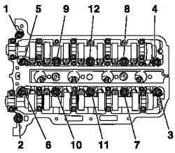
Fig. 2.223. Order otvorachivaniya
bolts fastening the cylinder head
Loosen the bolts fastening the cylinder head in the manner shown in Figure 2.223. Remove 12 bolts of 90 °. Remove 12 bolts of 180 °. Remove the cylinder head Start a chain tensioner for tire tension. Set cylinder head on the bars. Remove the cylinder head gasket. Remove the gasket body timing mechanism. Cut off the edge of the sealing elastomer (size II) construction of housing arrangement for gas distribution inside to the outside of a sharp knife and make flush with the cylinder block
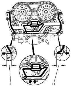
Fig. 2.224. Gasket valve timing
mechanism
Carefully bend the gasket at the points bending (arrows) (Fig. 2.224). Remove the remains of seals and sealing surfaces clean
NOTE Provide debris removal elastomer sealing edge of the space between the hull valve gear and cylinder block, as well as the timing mechanism of the case.
Fig. 2.225. Check the cylinder
head
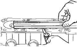
Check the cylinder head and cylinder block for flatness (Fig. 2.225). When testing or repairing the cylinder head, disconnect all external elements of the cylinder. Install the cylinder head gasket.
Cut off the protruding parts of elastomer (size I) by the mechanism of timing (see Figure 2.226).
Setting
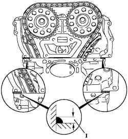
Fig. 2.227. The experimental setup
is laying on the hull valve timing mechanism
Apply sealer roller kremnievorganicheskogo (gray) on the hull valve gear / cylinder block thickness of approximately 2 mm (size I) (Fig. 2.227).
NOTE The head of the cylinder should be installed within 10 minutes after application of the silicon (gray) sealant and install bolts Corps timing mechanism.
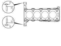
Install a new cylinder head gasket on the cylinder block. Labeling TOP must be at the top. Click on the gasket in the application of the silicon (gray) sealant.
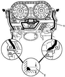
Fig. 2.228. The experimental setup
is laying on top of body mechanism Timing: 1 - upper gasket, 2 tourniquet
Install the upper body pad valve timing mechanism (Fig. 2.228). Set 2 (arrows) bolt housing timing mechanism. Install new gasket on the housing mechanism timing. Fasten the bolts. Click on the gasket in the application of the silicon (gray) sealant. Apply roller kremnievorganicheskogo sealant (gray) on the hull valve gear / cylinder block thickness of approximately 2 mm (the size I).
Set cylinder head
Enter a special tool KM-955-1 through a hole in the hull valve timing mechanism. Enter the timing chain on the tire tension. Insert the pin in the guide. Secure the cylinder head. Tighten the bolts fastening the new cylinder head for a few turns. Install casing timing mechanism.
NOTE Adjust the position of the cylinder head light rubber hammer blows in the direction of the shell valve timing mechanism.
Tighten the bolt 3 point 8 Nm 12 Tighten the mounting bolts of the cylinder head moment of 25 Nm, Dauvergne at +60 ° +60 ° +60 °.
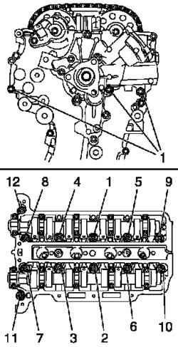
Fig. 2.229. The order of tightening
the bolts fastening the cylinder head
Pay attention to the proper tightening sequence (Fig. 2.229). Install the remaining components is carried out in reverse order of removal.


