4 minute read
Transmission, removing and installing on the engine (dismantled


Attach the front and rear of the gearbox to the engine and tighten the 2 screws mounting torque 60 N m. Set pan gearbox and tighten the 3 bolts fastening point 40 Nm Attach the front damping motor unit to the gearbox and tighten the 2 screws fastening the moment 80 Nm Set shafts of the wheels. Lift the engine and transmission with the help of a special device MKM-883-1.
NOTE When mounting the body of the front axle, make sure that the supporting bearing KM-6001-A properly located in the front guide pin damping engine block and rear brackets damping engine block. If necessary, adjust the loading position of the engine and gearbox, using a special device MKM-883-1.
Install the front axle housing.
NOTE Do not install the central silencer, front exhaust pipe, battery and battery support.
Replace the air filter housing and air intake hose. Install left damping engine block. Attach to the left relying damping engine block and tighten the 3 mounting bolts are 55 Nm Attach the gearbox to the top and tighten the 4 mounting bolt torque 60 Nm Connect the discharge pipe from the socket.
NOTE Cyanoacrylate clamp to latch.
Connect the wiring harness connector switch reversing lamps. Remove special device KM-6001-A from the body of the front axle. Install central silencer and a front exhaust pipe. Check the fluid level in the gearbox. Attach the bottom cover of the engine compartment.
NOTE If necessary, adjust the draft switching gear.
Install support battery. Replace the battery pack. Program volatile memory. Remove air from the hydraulic clutch.
Withdrawal
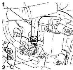
Fig. 3.40. Removing the coolant
hose from the thermostat housing: 1 - coolant hose, 2 - housing thermostat
Remove the coolant hose (1) with the thermostat housing (Fig. 3.40). Remove the clamp. Remove the hose from the coolant pump coolant.
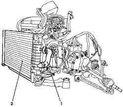
Fig. 3.41. Disabling the module
heatsink: 1 - coolant hose, 2 module heatsink
Disconnect the coolant hose from the body of the thermostat and turn off the module heat sink, pulling it from the lower radiator brackets (Figure 3.41).
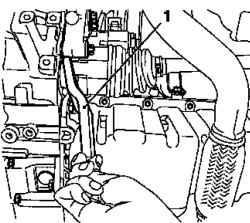
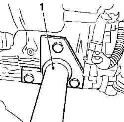
Fig. 3.42. Extract from the body
axis of the differential mechanism: 1 - a special device
Remove the body axis of the differential mechanism with the help of a special device KM-460-B (Figure 3.42). Hole in the differential close flap.
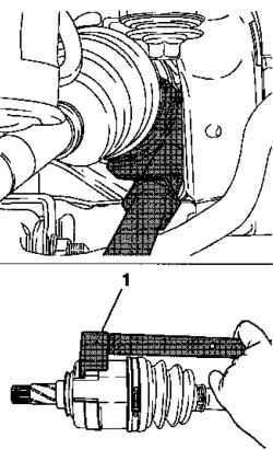
Fig. 3.43. Removing the left body
axis of the differential mechanism: 1 - a special device
Remove the left body axis of the differential mechanism with the help of special devices KM 313 and KM-6003-1 (Figure 3.43). Hole in the differential close cap
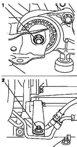
Fig. 3.44. Removing the front and
rear damping engine blocks: 1, 2 bolts fixing
Remove the front and rear damping block engine by unscrewing the bolts fastening (Figure 3.44). Remove the engine from the body of the front axle. Attach the cables to the motor vehicle footboards. Tighten up the engine hoist. Lift the engine.
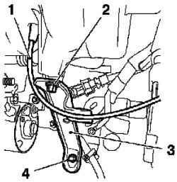
Fig. 3.45. Withdrawal of support
intake manifold: 1 - vacuum hose, 2, 4 - mounting screws, 3 - support
Remove prop intake manifold, disconnect the vacuum hose and unscrewing 2 screws fastening (Figure 3.45).
Install special device KM-412-31 and tighten the 3 mounting bolts (Figure 3.46).
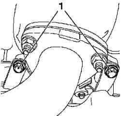
Fig. 3.47. Mounting bracket catalytic converter: 1 - Bolts
Remove the catalytic converter bracket by unscrewing 2 screws fastening (Figure 3.47). Unscrew the 2 screws fastening of the cylinder.
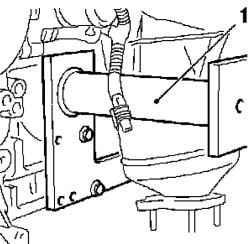
Fig. 3.48. Installation of special
devices: 1 - adaptation
Insert a special device KM-412-31 and tighten the 3 mounting bolts (Figure 3.48). Install the engine on the stand KM-412 and secure his 8 bolts. Disconnect the wires from the transport brackets. Remove the gearbox, remove the 6 mounting bolts.
NOTE One bolt is set to lock.
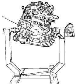
Fig. 3.49. Removing the gearbox: 1
- gearbox
Lift the gear box, loosen the bolt and remove the gearbox from the flange of the engine (Fig. 3.49).
NOTE Make sure that the adjacent components and wiring harnesses will not be damaged. Setting
Lift the gearbox. Attach the gearbox to the flange of the engine. Tighten the attachment bolt. Remove the cables. Secure the gearbox bolts. Transmission of the cylinder block - 4 bolt torque 60 Nm Transmission to the oil sump - 3boltami moment 40 Nm Lift the engine crane. Attach cables to transport footboards. Remove the engine from the stand of the CM-412, unscrewing 8 mounting bolts. Attach the intake manifold support by tightening the 2 screws fastening point 8 Nm Replace catalytic converter bracket by tightening the mounting bolts - on the catalytic converter element 15 Nm at the engine block moment 20 Nm Lift the engine. Gently pull down on the housing front axle. Unhook the motor from a crane. Remove the cables from the transport brackets. Install rear damping block engine. Use new bolts, tightening them are 55 Nm Install the front damping engine block. Use new bolts, tightening them are 55 Nm Install the left body axis.
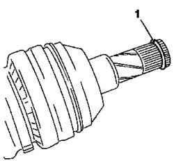
Fig. 3.50. Install the new retaining


