Applies to A20, A20C, A20C, A25, A25B 4x4, A25C, A25C, A30, A30C, A30C, A35, A35C, A35C, A35D, A40, A40, A40D,5350, 5350B, 860, 861
Action for reducing risk of fire
WARNING
Please pay attention to the safety instructions in the Operator's and Service Manuals concerned.
Regarding: General
It frequently happens that construction machines work in environments where inflammable material collects on the machines. Machine fires can be caused by different reasons, such as:
Heating up through the exhaust system
Sparking in the electrical system
To reduce the risk of fire, check the following points when carrying out maintenance work on the machine.
General
It is important that the machine is provided with suitable equipment to reduce the risk of inflammable material collecting on the machine in its working environment and then catching fire.
Examples of such equipment for Volvo BM wheel loaders are:
Guard over silencer.
Protective gauze for radiator to prevent collection and blockage by wood chips, sawdust and similar.
Cyclone pre-cleaner of turbo type to increase the cleaning capacity, particularly against coarse dust, sawdust, wood chips etc. This is self-emptying and is not connected to the ejector connection on the exhaust pipe. This connection is plugged, meaning that the spark extinguishing function of the silincer is still effective.
Keep the machine and equipment free from dirt, waste material, fuel and oil spillage.
Instruct the machine owner to keep the machine clean at all times.
NOTICE
If high-pressure washing is used for cleaning, take care not to damage the insulation on the electric leads, which can happen even at a relatively low water pressure and temperature.
Engine
Clean off all rubbish from the engine, particularly around the exhaust system, turbocharger and alternator.
Check that there is no fuel or oil leakage and that the hoses are clamped in such a way that no chafing occurs.
Fuel filling.
Take care when filling up with fuel that none is spilt outside the filling pipe.
Fuel mixed with dust and rubbish is a significant cause of fire.
If fuel has run out when filling up, wipe it up immediately. Do not fill upp with fuel near an open fire.
Electrical system
If the machines is left unattended, always turn off the battery disconnection switch.
Check the electric leads for abrasion and that they are not subjected to wear. This particularly applies to unfused leads, which are red and marked R (B+).
E. g., leads between:
Batteries
Battery and starter motor
Alternator and starter motor
Lead to engine starter element
In cases where these leads have been disconnected it is important to make sure that they are fittedand clamped in such a way that there is no risk of abrasion. Unfused leads must not come into contact with oil or fuel hoses.
When fitting any extra equipment, make sure that all leads are fused and arranged and clamped in such a way that there is no risk of abrasion.
CLICK HERE TO DOWNLOAD THE COMPLETE MANUAL
• Thank you very much for reading the preview of the manual.
• You can download the complete manual from: www.heydownloads.com by clicking the link below
• Please note: If there is no response to CLICKING the link, please download this PDF first and then click on it.
CLICK HERE TO DOWNLOAD THE
Clean off all rubbish.
Check that there is no oil leakage.
Brake system (hydraulic)
Check that there is no oil leakage and that pipes and hoses are protected, undamaged and properly clamped.
Protecting plates (bottom guard plates)
On machines such as compactors which are provided with bottom guard plates it is important that rubbish which has collectedinside and on the plates is removed every day.
The guard plates must be handled with care as they are very heavy. Instructions for correct handling of the plates can be found in the instruction book or supplement for the respective machine.
Hydraulic system
Check that threre is no leakage.
Welding
Take great care when carrying out welding work on the machine. Make sure that fire extinguishing equipment is available. Take particular care when welding close to fuel and oil lines and tanks.
If fire breaks out
At the slightest sign of fire, and if the situations permits, take the following action:
Drive the machine away from the hazardous area
Let down the lifting arms, dumper body etc to bottom position
Stop the engine with the stop control and turn the key switch to "O"-position
Get out of the cab
Turn off the main current with the battery disconnection switch
Start fire extinguishing work and alert the fire service if necessary
In connection with delivery instructions or at other service visits, please inform the owner/driver of the contents of thisService Bulletin.
Action to be taken in case of abnormal lubricating oil consumption
WARNING
Please pay attention to the safety instructions in the Operator's and Service Manuals concerned.
Introduction
The oil consumption is in many cases used as a measure of the condition of the engine. Normally all engines use a certain amount of oil. The film of oil that lubricates the upper piston rings is combusted at the same time as the fuel, which gradually causesthe oil level to drop. There are of course also other factors that affects the oil consumption, e.g. operating conditions and the conditionof the engine. Here follows a short description of influencing factors, checking and measuring methods and which action can be takento manage any problems.
Factors influencing the oil consumption
Larger engines have as a rule a higher oil consumption than small engines. Oil has the ability to penetrate the smallest openings. Therefore, proceed as follows:
Check for oil leakage around the engine and components
Check for oil leakage at the turbocharger
Check for oil leakage at induction manifold / charge air pipe
Take a lubricating oil sample
All affected bolts should be check-tightened.
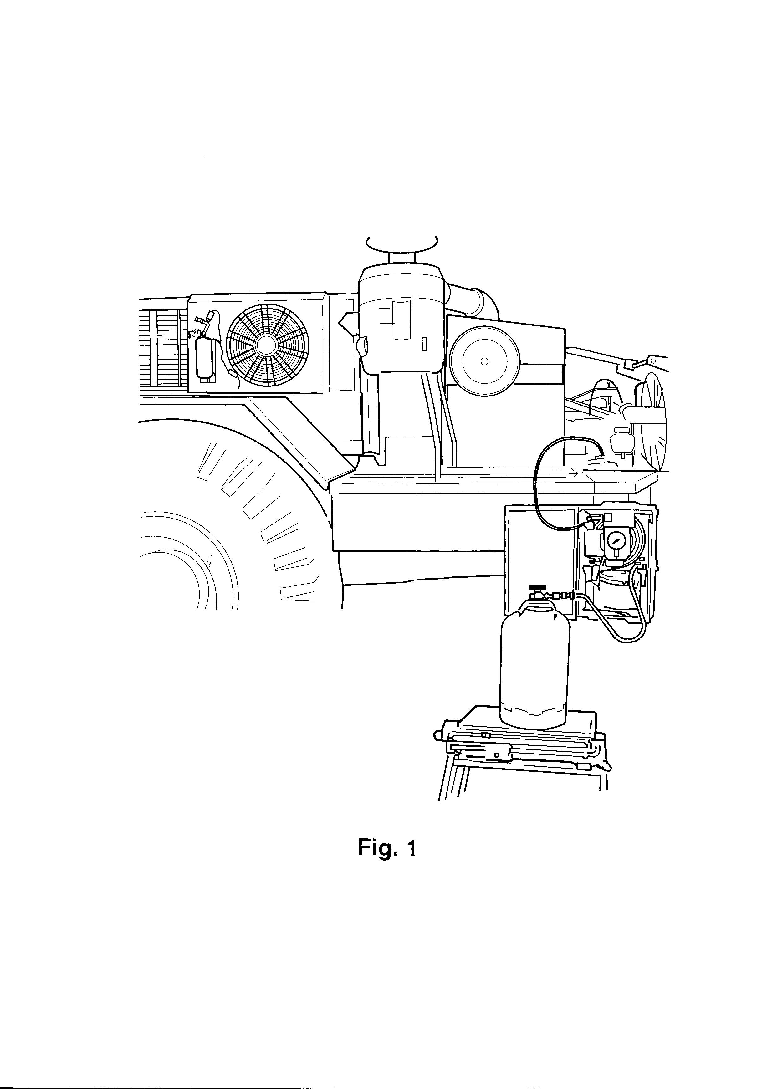
A too high oil level causes more oil to be thrown up on the cylinder walls and this increases the oil consumption. The oil level should be kept slightly below the full mark on the oil dipstick. Only check the oil level a few minutes after the engine has stoppedto allow the oil to run back to the sump, see Fig. 1.
Too thin oil will result in a higher oil consumption because of difficulties of maintaining a sealing film of oil between piston rings and cylinder wall at high temperatures. Too thick oil provides unsatisfactory lubrication and thereby increased wear, which in the long run will result in increased oil consumption. Always use the recommended oil grade and type according tothe Operator's Manual. Continuously high engine speed will result in warmer and thereby thinner oil. Increased oil consumption as described above. Frequent use of engine retarding causes increased oil consumption. Also long periods of idling / operating at low speed may cause increased oil consumption.
Faulty and worn piston rings, oil scraper rings, ring grooves, pistons, cylinders, valve guides result in high oil consumption, as oil leaks into the combustion chamber.
Abnormally low oil consumption
Some attention should also be given to low oil consumption, because the low oil consumption may beillusory. Used up oil may have been compensated through condensation water, coolant or fuel dilution, thus keeping the level unchanged. Intermixed coolant gives the oil a greyish tint, whereas intermixed fuel does not show. These factors result in impaired lubrication and should lead to more frequent oil changes. Intermixed fuel also mean an additional safety risk as the flash point of the oil is lowered. Take samples of lubricating oil and have them analysed.
Figure1
Checking and estimating oil consumption
The duration of the check / test period should be at least 250 hours (suitably between two oil changes and filter replacements) in order to avoid jumping to conclusions and taking unnecessary action. On an engine that has reached working temperature, the oil dipstick can be read off three minutes after stop. If the engine has been started, but not reached working temperature, wait for at least five minutes.
Copy the enclosed report form and make a note of the hour recorder reading at the start of the testperiod.
Begin with full fuel tank and new oil filled to the upper marking on oil the dipstick. Note the hour recorder reading and amounts every time you fill fuel, oil or coolant. Do not top up the oil until the level has reached the minimum line. Never fill oil to above the maximum line.
In case the oil is changed during the test period, check the oil level before draining and then fill to the same level. At the end of the test period, top up with oil to the maximum line and make a note of the amount.
Add up the noted information which then forms the base for calculating the oil consumption. The oil consumption is always stated as a relation between consumed oil and the amount of used fuel during the same period.
Example: An engine has during 250 hours used 18 litres of oil and 3000 litres of fuel. 18/3000 x 100 % = 0.6 %
Normal consumption
A new or fully overhauled engine often uses more oil than a run-in engine. Only after 1000–1500 operating hours, when the piston rings have bedded-in in the cylinders, is it possible correctly to determine the oil consumption.
Oil consumption of 0.3% or less = OK at full-load operation
Oil consumption of 0.3–0.75% = OK at light-load operation
If these limit values are exceeded, proceed as follows:
Carefully check the oil consumption (see instructions on the previous page) and contact the respective dealer regarding whether any action can be approved as a warranty job. A copy of the report form should be enclosed with the claim.
Date: 4/15/2016
Image id: 20204
Brand: Volvo BM Serial: 1-99999
Catalogue: 97311 Model: 5350B
Group/Section: 87/425
PROSIS Part Information
Title: Air compressor 98778, 98788
VOE98788 Pallet fork frame w fork postioner and fold in
VOE1593151 1
1 1
2 VOE1596024 1
3 VOE3522453 1 •O-ring (VOE1596026)
4 1
5 1
6 1
K •Screw
K •Washer
K •Clamp
7 VOE1698666 1 •Repair kit
VOE1698665 1 ••Gasket kit (VOE1695029)
8 VOE1308133 1
•Cylinder head
9 6 NS •Screw
10 VOE3522453 2 •O-ring (VOE1596026)
11 VOE1596025 2 •Valve
12 VOE1215459 2 •Valve cap
13 VOE3091323 1 •Sealing kit (VOE1695472)
14 1
1
ring
1
K
ring 22 REQ
K •Adjuster washer
23 VOE1695479 1
K •Key 24 1
K •Nut
VOE11992130 1 •Set
Applies to A25, 5350B
Air compressor filter
WARNING
Please pay attention to the safety instructions in the Operator's and Service Manuals concerned.
Regarding: 5350 B/A 25 w. e. f. serial no. 2761–
As an alternative to the air compressor filter, the suction inlet of the compressor can be connected to the engine air filter on 5350 B/A with effect from serial no. 2761–Work procedure
1 Remove the existing air compressor filter bracket, see Fig 1.
2 Cut the bracket to an angle of 45° and save the marked part, see Fig 1.
3 Remove suction pipe 1 of the engine air filter and remove sensor 2 from the pipe, see Fig 2.
4 Shape the saved piece from the air compressor bracket so that it matches the diameter of the engine air filter suction pipe.
Figure1
CLICK HERE TO DOWNLOAD THE COMPLETE MANUAL
• Thank you very much for reading the preview of the manual.
• You can download the complete manual from: www.heydownloads.com by clicking the link below
• Please note: If there is no response to CLICKING the link, please download this PDF first and then click on it.
CLICK HERE TO DOWNLOAD THE
5 Fit pipe piece 2 on the pipe according to the measurement shown in Fig 3. Mark out and drill a hole in the pipe, carefully remove all burr from the hole and weld pipe piece 2 on the pipe, see ----not implemented: INTXREF ----:
6 Plug all holes in the pipe and test for pressure.
NOTICE
There must be no leakage as this could result in serious damage to the engine. Thoroughly clean thepipe.
Figure2
7 Fit the pipe on the machine.
–Cut off a new suction hose for the compressor, length approx 2 m (78.7 in). The hose is suppliedby the metre under part no. 961195.
–Arrange the hose between the suction connection of the compressor and pipe piece on the engine air filter suction pipe. Use the existing hose clips. Clamp the hose with plastic clips or similar.
No compensation is given by Volvo BM for spare parts and labour.
Date: 4/15/2016
Image id: 16436B
Brand: Volvo BM Serial: 1-99999
Catalogue: 97311
Model: 5350B
PROSIS Part Information
Group/Section: 56/450 Title: Air compressor with fitting parts. SER NO -2760
1 VOE6210758 1
2 VOE1502685 1
3 VOE6642316 1
4 VOE6642317 1
5 VOE6642318 1
•Upper Section
••Bushing (VOE6642315)
••Bellows
•Sealing ring
•Brake valve VOE272571 1
••Repair Kit (VOE7272571)
CLICK HERE TO DOWNLOAD THE COMPLETE MANUAL
• Thank you very much for reading the preview of the manual.
• You can download the complete manual from: www.heydownloads.com by clicking the link below
• Please note: If there is no response to CLICKING the link, please download this PDF first and then click on it.
CLICK HERE TO DOWNLOAD THE
Date: 4/15/2016
Image id: 18607
Brand: Volvo BM Serial: 1-99999
Catalogue: 97311
Group/Section: 56/475
PROSIS Part Information
Model: 5350B
Title: Air compressor with fitting parts. SER NO 2761 -
2 VOE423087 1 Gear (VOE7423087)
3 VOE13975610 1 O-ring (VOE413619)
4 VOE953346 3 Stud
5 VOE955899 3 Washer
6 VOE13955828 3 Nut (VOE955828)
7 VOE943368 REQ Hose L=150
8 VOE943473 4 Hose clamp
9 VOE961606 1 OP Elbow nipple
10 VOE943368 REQ Hose L=530
11 VOE1576572 1 Pipe elbow
12 VOE1619957 1 Gasket (VOE7324359)
13 VOE13941907 2 Washer (VOE941907)
14 VOE13955295 2 Screw (VOE955295)
15 1 Pressure governor See ref 56/600
16 VOE1626068 1 Gasket (VOE7324042)
17 VOE13941907 2 Washer (VOE941907)
18 VOE955304 2 Hexagon screw
19 VOE180009 1 OP Nipple
20 VOE948055 1 Hose assembly
21 1 NS Air inlet
22 VOE1190349 1 Gasket
23 VOE4940432 1 OP Anchorage
24 VOE955892 2 Washer
25 VOE13946544 6 Screw (VOE946544)
26 VOE1591676 1 Non-return valve
27 VOE944364 2 O-ring
28 VOE13945915 3 Elbow nipple (VOE945915)L=400
29 VOE13945892 2 Nut (VOE945892)
29A VOE13946911 2 Nut (VOE946911)
30 VOE954364 3 Ferrule
31 VOE954356 3 Fitting nut
32 VOE4864058 1 OP Tube
33 VOE13945460 REQ Plastic pipe (VOE945460)L=250
34 VOE13945900 1 Nipple (VOE945900)
35 VOE13947281 6 Gasket (VOE947281)
36 VOE954364 2 Ferrule
37 VOE954356 2 Fitting nut
38 VOE947996 1 Nipple
39 VOE192272 1 Lock nut
40 VOE13945915 1 Elbow nipple (VOE945915)
41 VOE1578929 1 OP Contact
42 VOE946588 3 OP Plug
43 VOE952634 1 Clamp
44 VOE479979 1 Plug (VOE191026)
45 VOE927676 1 Elbow nipple
46 VOE944717 2 Sleeve (VOE967558)
47 VOE927660 REQ Rubber hose L=250
48 VOE13943474 2 Hose clamp (VOE943474)
49 VOE4940705 1 OP Anchorage
50 VOE11172907 1 Air filter (VOE4881323)
51 VOE941788 1 Clamp
52 VOE946671 1 Flange screw
53 VOE13945408 1 Nut (VOE948645)
54 VOE13945915 2 Elbow nipple (VOE945915)
55 VOE479956 1 Plug (VOE192154)
Date: 4/15/2016
Image id: 19924
Brand: Volvo BM Serial: 1-99999
Catalogue: 97311
Group/Section: 56/510
Model: 5350B
Title: Air compressor
PROSIS Part Information
1 1
2 VOE1518347 2
3 VOE1518346 2
4 VOE1696200 1
block
seat
Block
5 VOE1518350 1 ••Bushing
6 VOE1696201 1
7 6
8 6
•O-ring
•Screw
•Spring washer 9 1
10 VOE1697703 1
11 10
12 10
13 VOE1518353 1
•Gasket
•Spring washer
14 VOE7011014 1 •Ball Bearing
15 VOE7346520 1
16 VOE1518354 1
17 VOE1518355 1
Ring
•Spacer Ring
18 VOE1517545 1 •Key
19 VOE1518356 2 OP •Connecting Rod
20 VOE1518357 2
21 VOE7328738 2
22 VOE1697706 2
••Lock Washer
•Piston STD VOE1697707 2
•Piston 0.010"O SZ VOE3094153 2 •Piston (VOE1697708)0.020"O SZ
23 1
24 1
25 1
26 1
27 VOE1518371 2
••Piston ring
••Piston ring
••Piston ring
••Piston bolt
••Snap Ring
28 VOE3090473 1 •Valve Plate (VOE1518372)
29 VOE1697704 1 •Gasket
30 VOE1518374 1
•Cylinder head
31 VOE1697705 1 •Gasket
32 VOE1518376 11
•Screw VOE955278 2 •Hexagon screw (VOE1518377)
33 13
34 VOE1518378 1
•Spring washer
•Lock Pin 35 2
36 2
37 2
38 VOE1518686 2
•Valve spring
•Valve washer
•Piston
•O-ring 39 1
40 VOE11000155 1 •Pressure Plate
41 2
42 2
43 2
44 VOE479979 1
•Valve spring
•Valve washer
45 VOE3090471 1 Repair Kit (VOE270698)
46 VOE272896 1
VOE270613 1
VOE270614 1
SS Piston Ring Kit STD
SS Piston Ring Kit 0.010"O SZ
SS Piston Ring Kit 0.020"O SZ
Date: 4/15/2016
Image id: 16520A
Brand: Volvo BM Serial: 1-99999
Catalogue: 97311
Group/Section: 87/400
PROSIS Part Information
Model: 5350B
Title: Air conditioning, compressor, fitting.
2 VOE4941634 1 OP Bracket (VOE4774925)
VOE11055141 1 Bracket (VOE11055141)
3 VOE4823716 1 OP Tensioner
VOE943795 1 Allen Hd Screw (VOE4965103)
4 VOE13965185 4
Flange screw (EH965185)
VOE13970963 1 Hexagon screw
5 VOE13971098 4
VOE13971098 1
Flange nut (VOE13949279)
Flange nut
6 VOE955526 1 Screw
VOE13965183 1
Flange screw
7 VOE940161 2 Hexagon screw
VOE946472 2 Flange screw
8 VOE967133 1 V-belt (VOE958504)
VOE13977573 1 V-belt (VOE13967137)
Date: 4/15/2016 Image id: 16518 Catalogue: 97311 Model: 5350B
Brand: Volvo BM Serial: 1-99999
PROSIS Part Information
Group/Section: 87/350 Title: Air conditioning, condenser, fitting. 90519, 98777
7 VOE13964867 2 Bolt (VOE964867)
8 VOE976945 2
9 VOE907847 2
Washer (VOE960148)
Cotter Pin
10 VOE4823695 1 Anchorage
11 VOE13946173 6
Screw (VOE946173)
12 VOE13945408 4 Nut (VOE948645)
13 VOE940152 1
14 VOE13955900 1
15 VOE955860 1
16 VOE13955902 1
Hexagon nut
Washer (VOE955900)
Hexagon nut
Washer (VOE955902)
17 VOE925760 REQ Washer
18 VOE4823697 1 Anchorage
19 VOE13945444 2
Screw (VOE945444)
CLICK HERE TO DOWNLOAD THE COMPLETE MANUAL
• Thank you very much for reading the preview of the manual.
• You can download the complete manual from: www.heydownloads.com by clicking the link below
• Please note: If there is no response to CLICKING the link, please download this PDF first and then click on it.
CLICK HERE TO DOWNLOAD THE