14 minute read
Removing and installing the power unit (engine 2.0 l


Withdrawal
Open the hood. Disconnect the battery. Disconnect the connection with the mass withdrawal from the masses - loosen the nuts. Empty the climate installation. Connect the gas station. Connect the blue hose to the technology fitting the low-pressure small diameter. Connect the red hose to the fitting of high pressure technology of large diameter.
NOTE Carefully read the instruction manual petrol station. Determine the amount of refrigerant recovered from the oil separator gas station.
Remove the intermediate shaft steering column. To do this, the steering wheel in position rectilinear motion. Remove the ignition key and lock the steering wheel.
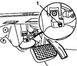
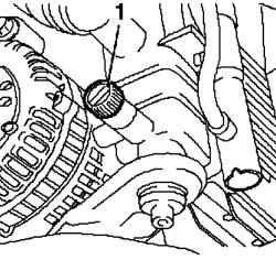
Fig. 2.126. Bolt kreleniya
intermediate shaft steering column: 1 - Bolt
Loosen the screw fastening (2.126). Remove the battery. Disconnect the positive lead from the positive terminal. Loosen the bolt mounting bracket and remove the battery.
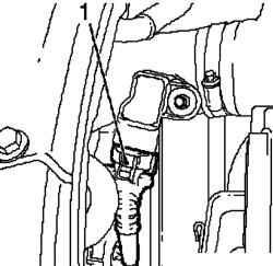
Fig. 2.127. Sensor wiring harness
connector boost pressure: 1 connector
Unplug the wiring harness connector boost pressure sensor (2.127). Disconnect the upper wiring harness module cooling. Disconnect the wiring harness connector. Disconnect the relay from the bracket. Remove the battery support.
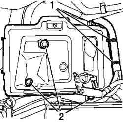
Disconnect the wiring harness to support the battery, remove the clamps for the wires and unscrew the 3 bolts (Fig. 2.128). Remove the air filter housing with the sensor mass air flow. Unplug the wiring harness connector sensor mass air flow iotsoedinite air intake hose inlet pipe. Disconnect brake booster vacuum line from the intake manifold
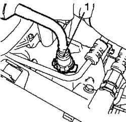
Fig. 2.129. Hose brake booster
vacuum line: 1 - hose
This quick-disconnect coupling and separate the vacuum line from the bracket (Fig. 2.129). Remove the intake manifold by unscrewing the bolt fastening. Loosen the clamp and remove the vent hose from the lid of the engine cylinder head. Loosen the clamp and disconnect the inlet pipe from the air intake hose. Disconnect the inlet pipe from the turbocharger.
NOTE Inlet pipe has a gasket in the turbo.
Remove the inlet pipe. Place the bottom of the container for collecting liquid.
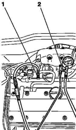
Reset the fuel pressure with the tool Specials KM-J-34730-91 through the test compound (Fig. 2.130).
NOTE
Collect leaking fuel into a suitable container, while respecting the rules of precaution.
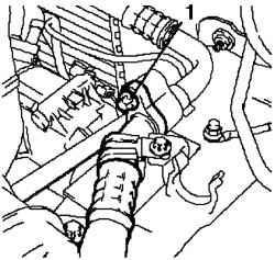
Fig. 2.131. Mounting fuel feedline: 1 -
the supply line 2 - nipple
Disconnect the supply line from the fuel rail by unscrewing the coupling nut (see Figure 2.131).

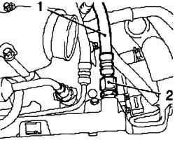
Fig. 2.132. Mounting fuel feedline:
1 - reverse pipeline; 2 - nipple, 3 Bracket
Disconnect the return fuel line from the fuel rail by unscrewing the coupling nut and disconnect the bracket (Fig. 2.132). Unplug the line of withdrawal vent the fuel tank.
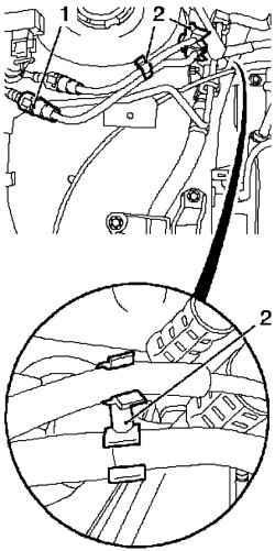
Fig. 2.133. Mounting withdrawal
line vent: 1 - a quick-coupling 2 bracket
Remove the quick release coupling with a special tool KM-796-A and disconnect from the bracket (Fig. 2.133). Disconnect the vacuum line from the turbocharger. Unplug the two lines and disconnect them from the bracket. Remove the grille by removing the four rivets. Remove the grille from the front shell top, removing the five clips. Loosen the front wheels. Raise the car in half. Remove the front wheels. Remove the front bumper, removing the rivets, five, and four clamping. Place the bottom of the container for collecting liquid.
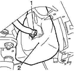
Fig. 2.134. Disconnecting the hose
high pressure headlamp cleaning system: 1 - high pressure hose, 2 - a quick-coupling
NOTICE This liquid is spilled from a hose.
Remove the front paneling.
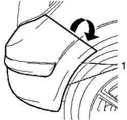
Fig. 2.135. Side mount front
bumper: 1 - Clamps
Pull the front lining up the side and remove from the bracket in the direction of the arrow (Fig. 2.135). Separate from the bumper bracket, disconnect 4 times. Disconnect and remove the outdoor sensor. Remove the right engine protection by unscrewing 4 bolts. Remove the two set out on the back of the rivets. Disconnect the levers on both sides of the supporting pipe rack spring by unscrewing the two nuts.
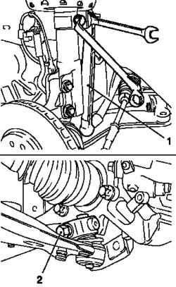
Fig. 2.136. Disconnecting from the
steering knuckle joints: 1 - lever, 2 bolts fixing
Remove the two hinges on the steering knuckle, unscrewing the two nuts and removing the two screws (Fig. 2.136). Extend pin steering knuckle using a special device KM-915 and remove the joint from the steering knuckle.
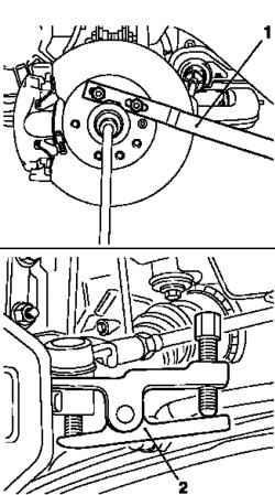
Fig. 2.137. Disconnect tie rod from
steering knuckle: 1, 2 - special arrangements
Disconnect the tie rod ends from steering knuckle using a special device KM-507-C (Fig. 2.137). Remove the shafts of the wheels of the wheel hub while holding the wheel hub with a special device KM-468-B (Fig. 2.137). Raise the car in half
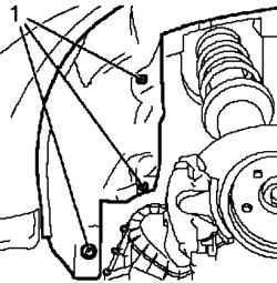
Fig. 2.138. Mounting upholstery
wheel arches: 1 - rivets
Remove the inner lining of wheel arches (left), taking out 3 rivets (Fig. 2.138). Unplug the wiring harness module cooling Unplug the mass wire by unscrewing the nut fastening. Unplug the wiring harness connector and remove it. Remove the wire clamps. Place the bottom of the container for collecting liquid. Drain the coolant.
To do this, loosen the drain bolt on the radiator (Fig. 2.139). Collect the coolant. Tighten the drain bolt. Unplug the wiring harness of oxygen sensor catalytic converter
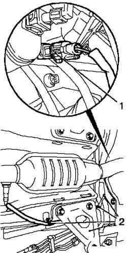
Fig. 2.140. Mounting the wiring
harness of oxygen sensor catalytic converter: 1 - the wiring harness connector, 2 - clamps
To do this, remove the wiring harness connector and Division 4 time (Fig. 2.140). Remove the front exhaust pipe. Disconnect the front exhaust pipe from the catalytic converter 3 unscrewing nuts.
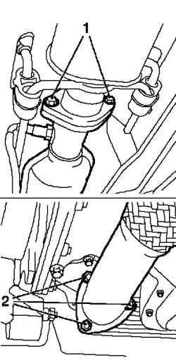
Disconnect the front exhaust pipe from the middle silencer unscrewing the two mounting screws (Fig. 2.141). Remove the right drive shaft.
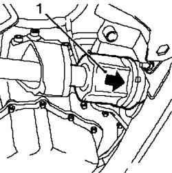
Fig. 2.142. Withdrawal of the right
shaft: 1 - drive shaft
NOTE Vybeyte in the direction of the arrow tool of soft metal (Fig. 2.142).
Insert special device KM-6173. Loosen the 4 bolts and tighten by hand. Align special device KM-6173 with the shell of the front axle. Enter your support.
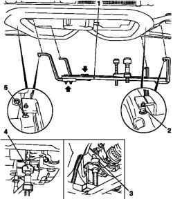
Fig. 2.143. Installation of a special
device KM-6001-A on the housing front axle: 1 - a special device, 2, 5 neck, 3 - rear support 4 - front support
Attach the KM-6001-A (Fig. 2.143).
NOTE Using the KM-6001-A ensures alignment with the drive housing the front axle.
Loosen the 3 bolts (arrows) in the adjustment tires. Insert special device KM-6001-A. Necks should be in the holes to the front axle housing. Tighten the 3 bolts fastening the adjustment in the tires. Adjust the support and lift them to the constraints on the neck guides.
NOTE Necks should be in the supports gapless.
Lower the car completely. Remove the coolant expansion tank from the bracket.
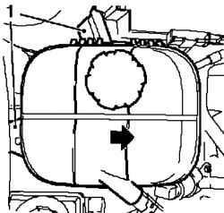
Fig. 2.144. Removing expansion
tank: 1 - tank
Remove the expansion tank from the bracket in the direction of the arrow. (Fig. 2.144). Unplug the two cable drive switching.

Separate from the bracket and separate from the guide lever (Fig. 2.145).
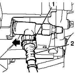
Fig. 2.146. Removing the central
discharge line on sump clutch: 1 clip 2 - the central flow line
Disconnect the central flow line of the crankcase clutch disconnecting the clamp in the direction of the arrow using a screwdriver (Fig. 2.146).
NOTE Wrap the ends of the pipe with a cloth.
Fig. 2.147. Disconnect the wiring
harness Steering: 1 - the wiring harness connector, 2 - nut, 3 brackets wiring harness
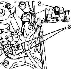
Unplug the wiring harness of steering control (Fig. 2.147). To do this, remove the fuse holder cover. Disconnect the positive cable from the fuse holder by unscrewing the nut fastening. Disconnect the wiring harness connector. Unplug the wiring harness.
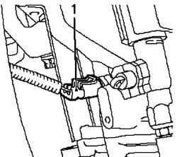
Fig. 2.148. The wiring harness
connector lamps reversing: 1 - the wiring harness connector
Unplug the wiring harness connector tubes reversing (Fig. 2.148). Disconnect the positive cable from the positive terminal, unscrewing bolts.
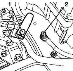
Fig. 2.149. Fastening wire body
mass: 1 - pin 2 - Nut
Unplug the lead from the body mass, turning away gaku attachment (Fig. 2.149). Unplug the wiring harness connector.
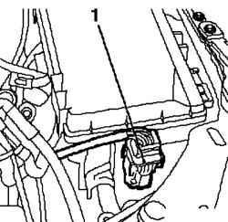
Fig. 2.150. Front wiring harness
connector to the holder of fuses: 1 connector
Disconnect the front wiring harness connector to the fuse holder (Fig. 2.150).
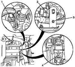
Fig. 2.151. Wiring harnesses,
engine: 1 - the wiring harness connector module engine management, 2 - the wiring harness connector oxygen sensor, 3 - wire clamps, 4 - the wiring harness connector
Unplug the wiring harness of the engine (Fig. 2.151). Disconnect the wiring harness of oxygen sensor (2) of the bracket. Disconnect the wiring harness connector. Disconnect the wiring harness connector module engine control. Remove the wire clamps.
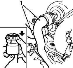
Fig. 2.152. Radiator Hoses: 1 -
Hoses
Disconnect the coolant hoses from the radiator heater (Fig. 2.152). Disconnect the upper and lower quick coupling.
NOTE Disconnect in the direction of the arrows in Figure 2.152.
Fig. 2.153. Line circuit cooling
system (low pressure side): 1 screw fixing
Disconnect the line circuit cooling system (low pressure side), unscrewing the bolt fastenings (Fig. 2.153). Unplug the line contour of the cooling system of the condenser 213
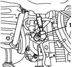
Fig. 2.154. Line circuit cooling
system (high pressure side): 1 screw fixing
Disconnect the line circuit cooling system (high pressure side), unscrewing the bolt fastenings (Fig. 2.154).
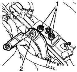
Fig. 2.155. Right damping motor
unit: 1 - damping block; 2 - bolts fixing
Disconnect the right damping motor unit from the adapter unit by unscrewing the bolt fastening 3 (Fig. 2.155).
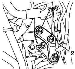
Fig. 2.156. Left damping motor
unit: 1 - damping block; 2 - bolts fixing
Disconnect the left damping motor unit from the adapter unit by unscrewing the bolt fastening 3 (Fig. 2.156).
Fixing the front axle on jack
Raise the car completely. Attach a special device KM 904 and KM 6390. Connect to the hydraulic lifter.
Fig. 2.157. Fixing the front axle on
jack: 1, 2 - pins
Vybeyte pins (see Figure 2.157). Remove the two pins. Podoprite housing front axle, make sure the reliability of support. Pins must enter the corresponding holes in the hull of the front axle.
Removing the body of the front axle
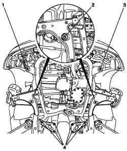
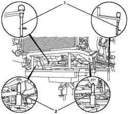
Fig. 2.158. Removing the body of the front axle: 1, 2,3,4 - bolts fixing
Remove the front axle housing by unscrewing 10 screws (1, 2, 3, 4) (Fig. 2.158).
NOTE Not be disassembled body of the front axle of a shock pulse or a screwdriver.
NOTE Bolts are different lengths. During disassembly of the shell of the front axle careful to not to damage the adjacent elements.
Pull the front axle housing.
Setting
Carefully move the front axle housing with the drive, steering mechanism and a radiator in the engine compartment and install the chassis without a gap.
NOTICE Not be disassembled body of the front axle of a shock pulse or screwdriver
Set the module to attach the new front axle bolts (1-4), torque 90 Nm +45 ° +15 ° (Fig. 2.158). Remove the special adaptations KM 904 and KM 6390. Lower the hydraulic jack. Disconnect the special adaptations KM 904 and KM 6100 by a hydraulic jack. Lower the car completely. Install the right damping motor unit to the adapter block and tighten the 3 bolts fastening force of 55 N m. Install the left engine damping block to the adapter block and tighten the 3 bolts fastening force of 55 N m. Attach the line circuit to the condenser cooling system and tighten the bolt fastening force of 20 N m.
NOTE Use a new gasket.
Attach the line circuit cooling system (low pressure side) and tighten the bolt fastening force of 20 N m.
NOTE Use a new gasket.
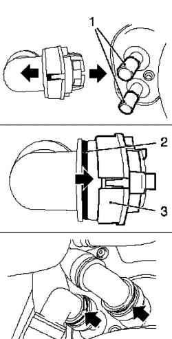
Connecting hoses of the cooling system
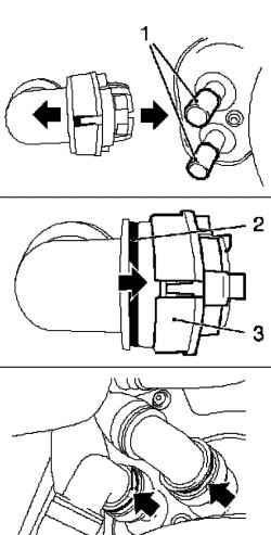
Fig. 2.159. Connecting the hoses
of the cooling system: 1 - socket radiator heater, 2 - clamps, 3 locking mechanism
Connect the hoses to the radiator cooling system heater (Fig. 2.159). Move the two locking mechanism of quick couplings in the direction of the arrow until it stops. Plastic (green) rings at the same will be closed.
NOTE Note the color marking.
Fig. 2.124. Connecting the hoses
of the cooling system: 1 - socket radiator heater, 2 - clamps, 3 locking mechanism
Move the two locking mechanism of quick couplings in the direction of the arrow until it stops (Fig. 2.124). Plastic (green) rings at the same will be closed. Ensure that quick release couplings are correct, and plastic rings (arrows) are visible. Connect the wiring harness of the engine. Connect the wiring harness engine control module. Attach 2 Hold time. Seal up the wire clamps. Connect the wiring harness. Attach the wiring harness connector oxygen sensor in the bracket. Connect the wiring harness to the fuse holder. Connect the wiring harness reverse gears and fasten it to the bracket. Connect the wire to the body mass. Connect the positive wire to the positive terminal. Connect the wiring harness of steering control. To do this, insert the wiring harness, to secure it in 2 brackets and wrapped nuts, connect the positive cable to the fuse holder Install the wiring harness connector. Replace the cover holder fuse Connect the central pipes on the crankcase clutch, quick-connecting coupling. 2 Connect the cable drive switch, to keep them in a bracket and installing the clamps. Lower the car completely. Select the right drive shaft into the intermediate shaft. Install the front exhaust pipe.
Attach the front exhaust pipe to the catalytic converter and tighten the 3 nuts effort 20 Nm Attach the front exhaust pipe to the middle silencer, secure it with two bolts. Connect the wiring harness of oxygen sensor catalytic converter. Lower the car in half. Connect the wiring harness module cooling. Install internal lining wheel arches. Set shafts of the wheels into the wheel hub.
NOTE During installation, hold the wheel hub with a special device KM-468-B.
2 Attach the hinge to the steering knuckle and tighten the effort of 50 N m.
NOTE Use with new nuts
Attach 2 of the lever to the supporting pipe rack and tighten the spring a new nut element 65 Nm
NOTE During the installation, use a wrench to hold the spring bar.
Attach 2 tie rod ends to the swivel and tighten new nut element 50 Nm Install the right engine splash guard Install the front bumper. Attach the outdoor sensor, cementing his time. Attach high pressure hose of the cleaner to a tank. Attach the quick release coupling to the windscreen washer reservoir. Install the front wheels. Lower the car in half. Fasten the bolts fastening the front wheels the moment 110 Nm Install radiator grille. Connect the vacuum line to the turbocharger. Connect 2 lines and secure them in a bracket. Attach the vent line of the fuel tank. Connect the quick coupling and secure it in a bracket. Connect the return fuel line to fuel rail Tighten the coupling nut and secure the return fuel line bracket. Connect the fuel line feeding to the fuel rail. Tighten the coupling nut. Install inlet pipe.
NOTE Remove the inlet pipe from the turbocharger outlet.
Remove the ventilation hose from the engine cylinder head cover and secure it ring. Attach the brake booster vacuum line to the intake manifold. Connect the quick coupling. Attach the vacuum line to the bracket. Replace the air filter housing with the sensor mass air flow. Insert the air filter housing. Attach the intake hose to the intake tube and secure it ring. Connect the wiring harness connector sensor mass air flow. Connect the device to pump the brakes to the valve pumping. Remove the valve cap. Connect the device MKM-6174-1 to the valve pumping. Install a device for pumping the brakes to the brake fluid reservoir. Install adapter device for pumping the brakes on the reservoir with brake fluid. Set device MKM-6174-2 on the adapter device for pumping the brakes. Remove air from the clutch. Turn on the device for pumping the brakes. Open the vent valve.


