3 minute read
Replacing the valve stems seals (installed cylinder head


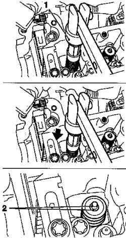
Attach special tool KM 6624 on the O-ring (Fig. 2.166). Tighten the bolt. Attach special tool KM-328-B of the CM 6624. Remove the O-ring with the help of special instruments KM-328-B, and KM 6624 (Fig. 2.166).
Setting
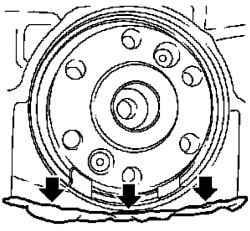
Fig. 2.167. Remains of seal
Remove the remnants of a sealant compound cylinder with oil pan (the arrows in Figure 2.167). Install new O-ring Slide the O-ring on the crankshaft. Slide to a complete and uniform planting in the engine block.
NOTE No O-ring is pressed fully.
Fig. 2.168. Installation omentum: 1
- a special tool KM 6623; 2 - fixing screws, 2 - screw fixing
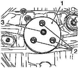
Install the O-ring with a special tool KM 6623 (Fig. 2.168). Tighten the 3 screws for fixation. Fully zapressuyte O-ring. Tighten the attachment bolt. Remove the special tool KM 6623 Loosen the 3 screws for fixation. Install the flywheel.
Withdrawal
Remove the camshafts. Remove the spark plug with a special tool KM-194-E. Raise the car. Remove the right engine splash guard.
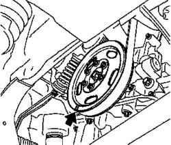
Can create the label on the belt pulley crank shaft (arrow in Figure 2.169).
NOTE Move to 180 ° relative to the label, TDC cylinder number 1.
Prepare a lever MKM-6086 to remove the valve springs. Adjust bearing special tool MKM-6086-6.
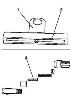
Fig. 2.170. Preparation of a special
tool for removing valve springs: 1 head support, 2 - stem bearing 3 hard part
Adjust the head bearings on the center on the leg supports and tighten (Fig. 2.170). Extend lever MKM-6086-7 joint MKM-6086-8, and a removable head MKM-6086-10. Install the unit MKM-6086-200. Set a stubborn part of the MKM-6086-200-10. Attach the lever for the valve springs MKM-6086. Attach the support MKM-6086-6. Insert the shaft in a block of support.
NOTE Align the shaft block with the center hole plugs
Tighten the 4 bolts fastening.
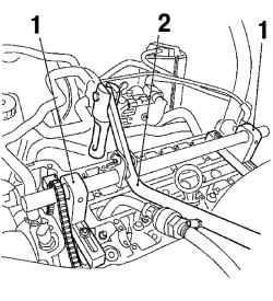
Fig. 2.171. Installation of the lever
and the poles to remove the valve springs: 1 - supports 2 - lever
NOTE Removable head should be towards the intake side.
Attach the installation shaft and tighten the 2 screws fastening. Install adapter compressed air. Replace the spark plug threads in the cylinder number 1. Give compressed air into the cylinder number 1. Remove 2 springs intake valve cylinder number 1.
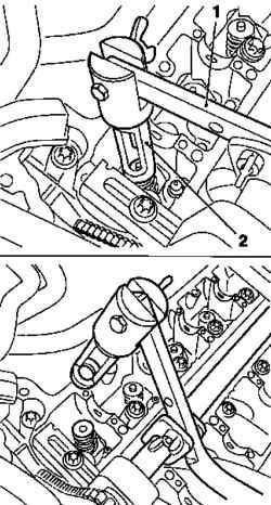
Fig. 2.172. The procedure for
compression of valve springs: 1 lever, 2 - Removable Head
Gently pull down the lever valve springs (Fig. 2.172).
NOTE Removable head (Fig. 2.172) should be placed vertically above the valve stem.
NOTICE Observe the correct installation.
Remove the biscuits and the valve head, valve springs.
NOTE Do not use with magnetic tools.
Replace valve stem seals.
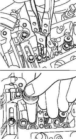
Place the new seal valve stem on the valve stem (Fig. 2.173). Put all the way through the CM 958. Install the intake valve springs, cylinder number 1. Install valve springs and valve heads. Install biscuits in the valve cylinder head.
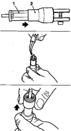
Fig. 2.174. Installing the valve in
the head biscuits installation unit: 1 - biscuit valve, 2 - plastic collet
NOTICE Set biscuits offset by the end of the cone in the direction of the valve
Slide the plastic collet in the direction of the valve (arrow in Figure 2.174). Attach the installation head to the lever.
NOTICE The head should be positioned vertically above the valve stem. Rusk must log on seat with the click.
Fig. 2.175. Installing crackers
valves and valve springs: 1 - head, 2 - biscuits
Carefully slide the valve springs down with a lever (arrow in Figure 2.175).
NOTICE Do not make the 2-S attempt, without making sure that the two biscuit installed in the cylinder head. Make sure landing crumbs. Ensure supply of compressed air.
Move the lever and remove it. Perform this procedure to all cylinders. Shut off the supply line of compressed air Unlock the crankshaft. Install the piston cylinder number 3 in the position of TDC. Pull the chain drive mechanism for timing up. Evenly, rotate the crankshaft (180 °).
Lock the crankshaft with a special tool KM-952. Relocate adapter supply of compressed air. Shut off the supply line of compressed air. Unscrew the adapter from the spark plug threads, cylinder number 4.


