4 minute read
Checking the pressure loss in the engine (1,8 l


Apply a layer of silicone sealant (gray) with a thickness of about 2 mm (the size I) in place of the body synchronization and the cylinder head.
NOTICE Visually check the bolts and make sure the seal is not damaged. If necessary, replace the bolts with new ones.
Tighten the mounting bolts 13 point 8 Nm Replace ignition module. Connect the module to the spark plugs. Tighten the two screws fastening point 8 Nm Install the ignition module cover on the lid of the cylinder head. Connect the wiring harness ignition module. Attach the wiring harness on the lid of the cylinder head. Connect the camshaft sensor, mass airflow sensor, pressure sensor oil and coolant temperature sensor. Replace the air filter housing on the arch of the wheel and tighten the attachment bolt. Attach the intake hose to throttle module and attach the clamp. Attach the hose to the ventilation of the engine air intake hose and secure clamp. Connect the wiring harness to the sensor air flow mass. Connect the ventilation pipe of the fuel tank. Close the hood.
Removing the air filter housing
Open the hood.
NOTE Before the verification procedure warming up the engine to operating temperature (oil temperature - 80 ° C).
Loosen nuts and remove the massive wire from the battery. Remove the air filter housing and intake manifold.
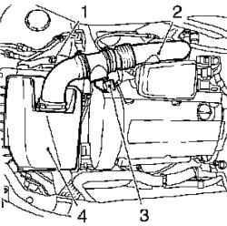
Fig. 2.44. Components, shooting
in the dismantling of the air filter: 1 attachment bolt, 2 - inlet manifold, 3 - the wiring harness connector sensor mass air flow, 4 - air filter housing
Disconnect the wiring harness connector sensor mass air flow.
Loosen the mounting bolt, remove the collar and the inlet pipe of air filter.
Removing the front cover toothed belt
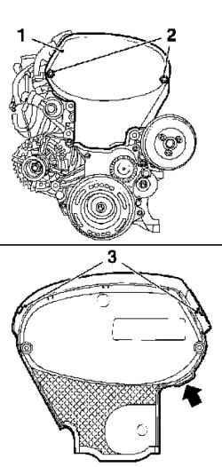
Fig. 2.45. Mounting the front cover
toothed belt: 1 - the front cover of the toothed belt 2 - mounting screws, 3 - Latch
Loosen the two mounting screws, disconnect the upper latch and remove the front cover of the toothed belt (top) (Figure 2.45).
NOTE Pull the front cover of the toothed belt upwards, the protrusion (arrow in Figure 2.45).
Remove the ignition module in the direction of the arrow shown therein.
NOTE Mark the position of arrows on the lid.
Fig. 2.46. Removing the ignition
module: 1 - bolts fastening
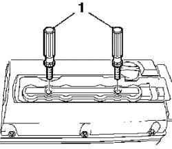
Unscrewing 2 screws, remove the spark plug, using a special tool KM 6009 (Fig. 2.46). Remove the coolant expansion tank.
Withdrawal right boryzgovika Engine
Loosen the 4 bolts and remove the attachment right mudflap engine.
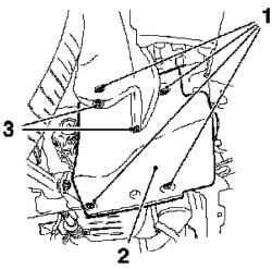
Fig. 2.47. Components, Removable
cover for dismantling the cylinder head: 1 - right engine splash guard, 2 - mounting screws, 3 - rivets
Remove the two set out on the back of the rivets.
Install the crankshaft position at top dead center (TDC), piston cylinder number 1
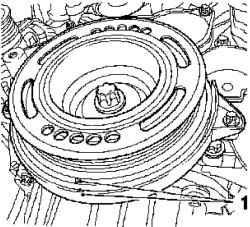
Fig. 2.48. Install the crankshaft position at top dead center (TDC), piston cylinder number 1: 1 - Tags
Rotate the crankshaft of the engine in the direction of rotation, set the piston cylinder number 1 in the position of top dead center (TDC) (mark 1) (Figure 2.48). Lower the car.
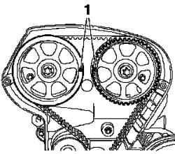
Fig. 2.49. The combination of
marks on camshaft gears: 1 - Tags
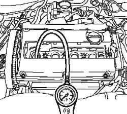
Connect the tester to the system pressure drop, the compressed air (Figure 2.50). Calibrate the tester pressure drop. Turn prvuyu transfer and parking brake systems.
NOTE The wheels must be in contact with the ground.
Replace the connection piece into the threaded hole plugs cylinder number 1. File a compressed air into the cylinder.
Check the pressure drop
Determine the value of pressure drop. The maximum allowable pressure difference between the cylinders - approximately 10%. Maximum loss of pressure in the cylinder - 25%.
NOTE Watch for any visible leaks of compressed air in the intake and exhaust manifold and the crankcase. Pay attention to the bubbles in the coolant expansion tank.
Rotate the crankshaft 180 ° in the direction of motor rotation (corresponding to 90 ° rotation of cam gear) and set the piston cylinder number 3 in the position of top dead center (TDC) (pre-stamped label). Connect the tester pressure drop. Replace the connection piece into the threaded hole plugs cylinder number 3 and submit the compressed air into the cylinder. Determine the value of pressure drop. The maximum allowable pressure difference between the cylinders - approximately 10%. Maximum loss of pressure in the cylinder - 25%. Rotate the crankshaft 180 ° in the direction of motor rotation (corresponding to 90 ° rotation of cam gear) and set the piston cylinder number 4 in the position of top dead center (TDC) (pre-stamped label) Connect the tester pressure drop. Replace the connection piece into the threaded hole plugs cylinder number 4, and submit the compressed air into the cylinder. Determine the value of pressure drop. The maximum allowable pressure difference between the cylinders - approximately 10%. Maximum loss of pressure in the cylinder - 25%. Rotate the crankshaft 180 ° in the direction of motor rotation (corresponding to 90 ° rotation of cam gear) and set the piston cylinder number 2 in the position of top dead center (TDC) (pre-stamped label) Connect the tester pressure drop. Replace the connection piece into the threaded hole plugs cylinder number 2 and submit the compressed air into the cylinder. Determine the value of pressure drop. The maximum allowable pressure difference between the cylinders - approximately 10%. Maximum loss of pressure in the cylinder - 25%. 159


