5 minute read
Checking the pressure loss in the engine (1,4-1,6 l


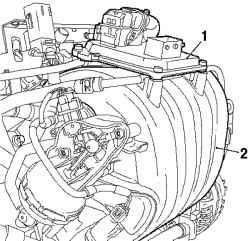
Fig. 2.34. Mounting electronic
module: 1 - an electronic control module engine Simtec 75.1; 2 - inlet manifold
Features
Engine management system has the following differences from the engine systems Z 18 XE and Z 16 XEP: - Installed PCB - printed circuit board; - Set the second sensor camshaft; - Set the second temperature sensor.
2.2. Petrol engines - general inspection procedures
2.2.1. General
The Test values for all engines, see Table. 2.2, Table. 2.3, Table. 2.3, Table. 2.4, Table. 2.5
Checking the pressure loss in the engine (1,4-1,6 l)
Removing the air filter housing
Open the hood
NOTE Before the verification procedure warming up the engine to operating temperature (oil temperature - 80 ° C).
Fig. 2.35. Components, shooting
in the dismantling of the air filter: 1 screw fixing the lower rubber support, 2 - wiring harness mass air flow sensor, and 3 - line of ventilation of the fuel tank, 4 - hose, ventilation motor, 5 - air intake hose, 6 - inlet pipe
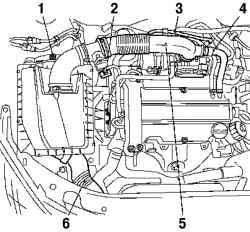
Remove the air filter housing (Fig. 2.35). Disconnect the wiring harness sensor mass air flow. Disconnect the fuel tank ventilation line. Disconnect the ventilation hose from the engine air intake hose. Removing the clamp, disconnect the hose from the air intake throttle pipe. Removing the clamp, remove the air filter housing. Loosen the screw fixing the lower rubber support and unplug it. Disconnect the inlet pipe.
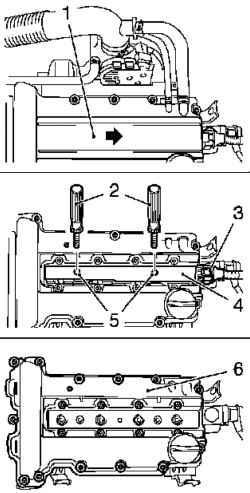
Fig. 2.36. Components shooting in
dismantling the ignition module: 1 ignition module cover, 2 - a special tool; 3 - Ignition module wiring harness, 4 - ignition module 5 mounting screws, 6 - cylinder head cover
Remove the ignition module with the lid of the cylinder head in the direction strelki.2
Loosen the two bolts. Separate the ignition module from the spark plug with a special tool KM-6009 2.
Removing the camshaft sensor
Disconnect connectors camshaft sensor, film mass airflow sensor, pressure sensor oil and coolant temperature sensor.
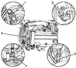
Fig. 2.37. Components shooting in
dismantling the camshaft sensor: 1 - camshaft sensor connector, 2 plug the sensor mass air flow, 3 - oil pressure sensor connector, 4 - slot coolant temperature sensor, 5 posting
Disconnect the wires from the lid of the cylinder head.
Take it back.
Removing the cylinder head
Remove the two clamp and disconnect the hose from the cover of the engine cylinder head. Disconnect the wiring harness connector module plugs. Remove the ignition module with the lid of the cylinder head in the direction of the arrow. Loosen the two bolts.
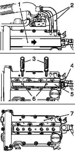
Fig. 2.38. Components, Removable
cover for dismantling the cylinder head: 1 - ignition module cover, 2 Hoses Engine 3 - the wiring harness ignition module 4 - module wiring harness connector plugs, 5 ignition module, 6 - bolt mount; 7 - a special tool
Separate the ignition module from the spark plug with a special tool KM-6009 3.
Remove the cylinder head. Loosen the mounting bolts 13. Remove the remains of seals and sealing surfaces clean. Remove the spark plug with a special tool KM-194-E.
NOTICE Open the lid carefully and slowly. There is a risk of burns.
Unscrew the expansion tank coolant. Remove the oil dipstick. Raise the car.
Withdrawal right boryzgovika Engine
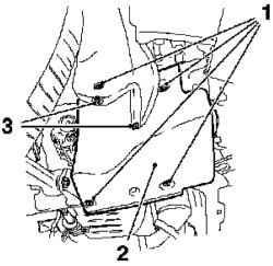
Fig. 2.39. Components, Removable
cover for dismantling the cylinder head: 1 - right engine splash guard, 2 - mounting screws, 3 - rivets
Remove the two set out on the back of the rivets.
Install the crankshaft position at top dead center (TDC), piston cylinder number 1
Fig. 2.40. Install the crankshaft
position at top dead center (TDC), piston cylinder number 1: 1 - cams cylinder number 1, 2 - lug 3 - Tag
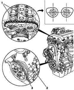
Use a bolt on the hub of the crankshaft for installation of the crankshaft in the position of top dead center (TDC), piston cylinder number 1 in the direction of rotation of the engine. Check belt pulley on the crankshaft must be aligned with the projection on the case.
NOTE In this position the number 1 cylinder cams are located in the TDC (both cam facing outwards).
Fig. 2.41. The shift marks on the belt pulley
of 180 ° relative to the TDC marks the first cylinder
Move the label on the belt pulley of 180 ° relative to the TDC marks the first cylinder (arrow) (Figure 2.41). Lower the car.
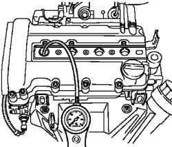
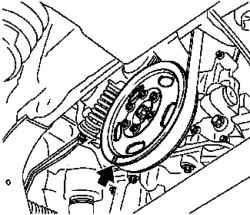
Fig. 2.42. Connecting tester
Connect the tester to the system pressure drop, the compressed air (Figure 2.42). Calibrate the tester pressure drop.
Replace the connection piece in the candle hole cylinder number 1 and plug the tester pressure drop to the adapter (in accordance with the manufacturer's instruction). Select a program and turn the hand brake.
NOTE All wheels must touch the ground.
On the automatic transmission, move the selector lever to position «P». Check the pressure drop in cylinder number 1. Consider the testimony of pressure drop on the tester as a percentage.
NOTE Pay attention to any noise from the leakage of air from the intake manifold, exhaust system or sump, as well as bubbles in the expansion tank cooling system.
Set the crankshaft in the position of ignition in the cylinder number 3 (TDC). Check the pressure drop in the cylinder number 3. Set the crankshaft in the position of ignition in the cylinder number 4 (TDC). Check the pressure drop in cylinder number 4. Set the crankshaft in the position of ignition in the cylinder number 2 (TDC). Check the pressure drop in cylinder number 2. Compare the results. Maximum pressure variation between the individual cylinders is about 10%. Maximum pressure drop in a separate cylinder should not exceed 25%.
Installation components
Raise the car. Attach the right engine splash guard. Tighten the 4 bolts. Install two rivets. Lower the car. Replace the cover expansion tank coolant and oil dipstick. Replace spark plug with a special tool KM-194-E in the cylinder head and tighten the moment 25 Nm
Replacing cylinder head
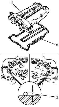
Fig. 2.43. Replacing Cylinder head:
1 - cover of the cylinder head, 2 Seal
Replace the cover cylinder head. Replace gasket.


