3 minute read
Replacing the steering column


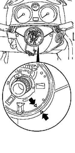
NOTE Contact module can not twist when lifting. When removing and installing, make sure that the label (arrows) are located opposite each other, as shown in Figure 5.16.
Setting
Set column module (CIM). Connect and lock the wiring harness connector and attach the wiring harness in the holder. Tighten the 3 bolts. Attach the bottom facing the steering column. Install the ignition socket and tighten the 5 screws fastening. Install the steering. Connect the battery pack.
NOTE When replacing the control unit, after connecting the control unit, do programming with the instrument CLOSE 2.
Program volatile memory.
NOTE Before installing the system, acting upon the air bag, observe security measures for pyrotechnic systems.
Withdrawal
Lock the steering Set the steering in the position of the rectilinear motion. Remove the ignition key. Give the trigger lock the steering column. Remove the pad upholstery of the driver.
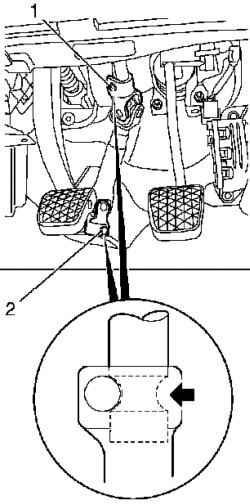
2 Loosen the clamp bolt (Figure 5.17).
NOTE Check the loading position, clamping bolts.
Remove the intermediate shaft slightly squeezing it. Disconnect the mass wire from the battery.
NOTE Wait 1 Mindl discharge the capacitor.
Remove the air bag module.
NOTE Module air bag should not be subjected to excessive loads, and should always be placed face up.
Separate wiring harness connector audio signal.
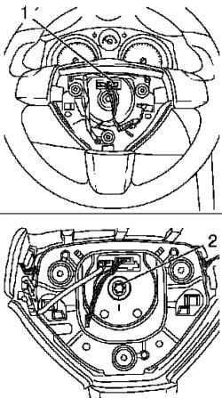
Remove the steering wheel with power steering column, unscrewing fastening bolt (Figure 5.18). Remove the steering wheel from the steering shaft. Remove the top upholstery of the steering column by unscrewing 2 screws fastening. Remove the lining of the lower steering column, 3 unscrewing bolts. Remove the module CIM, separating the wiring harness connector and unscrewing 3 bolts. Remove the light switch module.
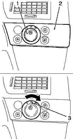
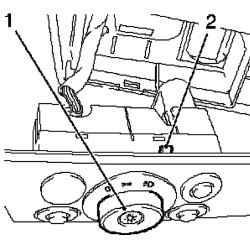
Fig. 5.19. Removing the module
light switch: 1 - Grip 2 - central location, 3 - light switch module
NOTE To remove the light switch module, to drown the handle (1) in position "0", move the knob to the center position and remove the light switch module (Fig. 5.19).
Remove the light switch module.
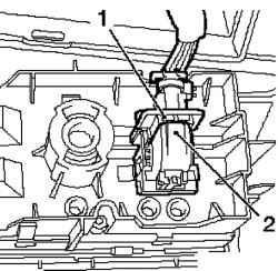
Fig. 5.20. Removing the wiring
harness connector module light switch: 1 - secondary fuse, 2 - fuse
Separate wiring harness connector module light switch. To do this, push the secondary fuse and unlock the fuse (Figure 5.20). Remove the bottom pad of the instrument panel by unscrewing 4 bolts fastening. Remove the wiring harness power steering column, unscrewing bolts. Remove the steering column with the cross, turning away 3bolta attachment.
NOTE Check the loading position cotter pin at the top of the steering column.
Remove the steering / ignition unit with the steering column. Turn the ignition switch to the starting position.
Setting
Attach the steering / ignition switch to the block of the steering column. Install and tighten the clamp bolts. Attach the power steering column to the crossbar and then block the steering column, tighten the 3 bolts.
NOTE Cotter pin must be properly installed in the crossbar.
Attach the wiring harness to the block of the steering column. Attach the wiring harness in the holder. Lock the steering. Install the steering column in the position of the rectilinear motion. Check on the steering column should be turned down. Remove the key from the ignition. Give the trigger lock the steering column. Install the lower instrument panel pad. Connect the wiring harness connector module light switch. Install light switch module.
Free module switch light. To do this, turn the rotary switch to position "0", fix the light switch (Figure 5.21). Install module CIM. Connect the wiring harness connector. Install the bottom facing the steering column. Install the upper facing of the steering column. Insert the wiring harness air bag through the hole in the steering wheel hub. Attach the steering wheel to the steering shaft. Install the steering wheel on the block steering column.
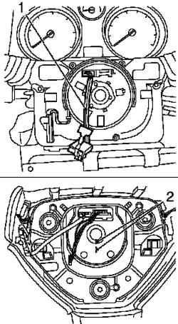
Fig. 5.22. The combination of tags
on the steering wheel and the steering shaft: 1 - wiring harness inflatable airbags, 2 - tags
NOTE Align the mark on the steering wheel and the steering shaft (Fig. 5.22).
Tighten the attachment bolt moment 30 Nm


