1 minute read
Measurement of radial and lateral runout of the bearing wheels


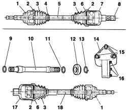
Fig. 3.99. The drive shaft with
internal tripodnogo type constant velocity joints and intermediate shaft: 1 - outer constant velocity joints (double compensation); 2 Mounting clamp, 3 - anthers 4 Mounting clamp, 5 - left drive shaft; 6 - circlip hinge; 7 - inner CV Joints tripodnogo type 8 - snap ring, 9 - Oring, 10 - intermediate shaft; 11 locking ring, 12 - journal-bearing intermediate shaft; 13 - locking ring, 14 - intermediate support 15 - fixing screws intermediate support 16 - tie intermediate shaft flange bolts, 17 inner CV Joints tripodnogo type (with slots for intermediate shaft), 18 - right drive shaft
Carry case must periodically inspect for the presence of traces of damage, leakage of the lubricant or cuts. Damaged covers CV Joints must be immediately replaced by new ones, otherwise the constant velocity joints can be damaged. Replacing the cover includes the operation of removing drive shafts. The signs of wear or damage to the constant velocity joints, in addition to leakage of the lubricant, are snapping when moving and turning, the roar when accelerating after a motion by inertia or vibration at high speeds on the highway.
Withdrawal
Remove the rear wheel. Remove the brake disc or brake drum.
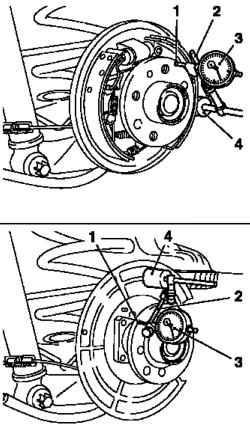
Fig. 3.100. Measurement of the
radial runout: 1 - The clock display type sensor 2 - LED clock type 3 - a special tool, 4 - magnetic holder
Attach special tool MKM-571-B with bracket clock-type indicator and a magnetic holder to the brake shield or cover (Fig. 3.100). Install sensor type indicator hour in front of the outer edge of the bearing wheels. Set the indicator to "0".


