14 minute read
Removing and installing the power unit (engine 1.4 l


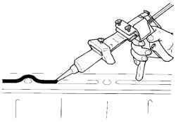
After the operation put the new sealant (Fig. 2.91). Try to use proprietary sealant or equivalent. After laying a new sealant wait 5 minutes and then mate. Remove excess sealant piece of matter. Tighten mounting bolts.
Withdrawal
Open the hood. Remove the intermediate axis of the steering column. To do this, the steering wheel in position rectilinear motion. Remove the ignition key and lock the steering column.
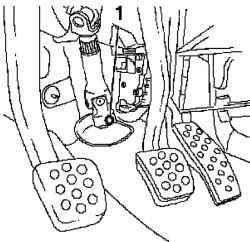
Fig. 2.92. Bolt fixing the steering
column: 1 - Bolt
Loosen the mounting bolt (Figure 2.92).
Removing the air filter housing
Open the hood.
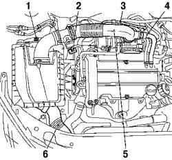
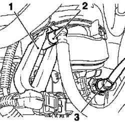
Fig. 2.93. Components, shooting
in the dismantling of the air filter: 1 screw fixing the lower rubber support, 2 - wiring harness mass air flow sensor, and 3 - line of ventilation of the fuel tank, 4 - hose, ventilation motor, 5 - air intake hose, 6 - inlet pipe
Remove the air filter housing (Fig. 2.93).
Disconnect the wiring harness sensor mass air flow. Disconnect the fuel tank ventilation line. Disconnect the ventilation hose from the engine air intake hose. Removing the clamp, disconnect the hose from the air intake throttle pipe. Removing the clamp, remove the air filter housing Loosen the screw fixing the lower rubber support and unplug it. Disconnect the inlet pipe.
Disconnect the wires "masses" and the battery power
Fig. 2.94. Wires "weight" and
feeding the battery: 1 - the positive terminal, 2 - the positive wire, 3 finding the "masses", 4, 5 - wire "mass"
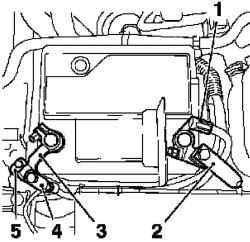
Disconnect the wires from the massive withdrawal of the "masses" unscrewing the two mounting screws (Figure 2.94). Loosen the bolt and disconnect the wire from the negative terminals of the battery. Disconnect the positive lead from the positive terminal.
Removing the battery and supports
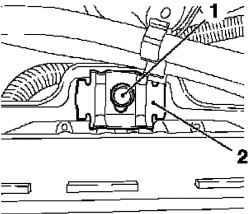
Fig. 2.95. Mounting the battery: 1 -
pin 2 - spud
Remove the battery by unscrewing the bolt and removing the strap (Figure 2.95).
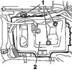
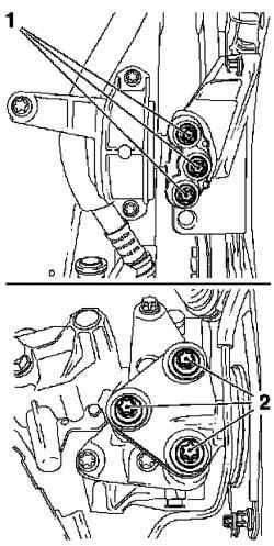
Fig. 2.96. Support Battery: 1 -
mounting screws, 2 - prop
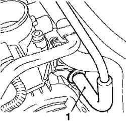
Fig. 2.97. Hose ventilation valve
tank: 1 - hose
Disconnect the ventilation hose from the exhaust valve of the tank (Fig. 2.97).
Reset the fuel pressure
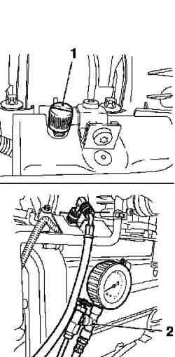
Fig. 2.98. Reset the fuel pressure:
1 - a protective cover, 2 - a special device
Reset the fuel pressure with a special device KM-J-34730-91 through the test jumper (see Figure 2.98).
NOTE
Collect withdrawing fuel in a suitable container - while adhering to safety precautions.
Remove the protective cover (Figure 2.98).
Fig. 2.99. Wires "weight" and
feeding the battery: 1 - a special device, 2 - feeding the fuel line, 3 vacuum brake booster line
Disconnect the fuel line feeding from the fuel rail with a special device KM-796 (Fig. 2.99). Disconnect the quick release coupling. Disconnect brake booster vacuum line from the intake manifold. Disconnect the quick release coupling.
Removing the engine control module and wiring harnesses
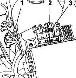
Fig. 2.100. Wires "weight" and
feeding the battery: 1 - the wiring harness connector, 2 - the wiring harness connector, 3 - Holder, 4 module for motor control
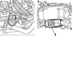
Disconnect the wiring harness of the engine (Fig. 2.100). Disconnect the holder in the direction of the arrow. Remove the wire clamps. Disconnect the engine control module and wiring harness connectors (Fig. 2.100).
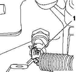
Fig. 2.101. Wiring harness
connector switch reversing: 1 connector
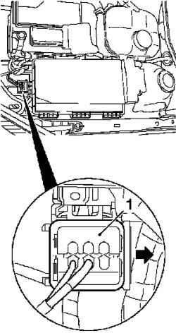
Fig. 2.102. Connector wiring
harness weight: 1 - holder
To release the holder in the direction of the arrow (Fig. 2.102). Remove the coolant expansion tank.
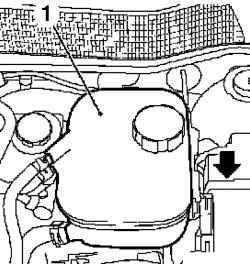
Fig. 2.103. Removing the bracket
expansion tank coolant: 1 - tank
Remove the bracket in the direction of the arrow (Fig. 2.103). Disconnect the wiring harness of steering control. To do this, remove the cover mounting element fuse. Disconnect the positive lead from the fastening element fuse. Loosen nuts.
Disconnect the wiring harness connector (Fig. 2.104).
Removing the central hose
Unplug the central hose. Place the bottom of the container.
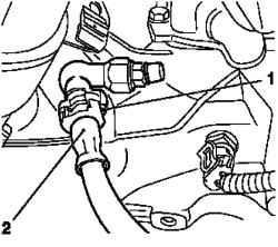
Fig. 2.105. Central hose: 1 -
holding the collar, 2 - hose
Unlock and remove the retaining clamp with a screwdriver (Fig. 2.105). Bend the clip and insert back into the connector. Podvyazhite central flow line.
Removing the grille
Loosen the 8 bolts secure the front wheels. Raise the car in half. Loosen the 8 screws and remove the front wheels. Remove the 4 rivets and grille.
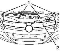
Fig. 2.106. Removing the grille: 1 -
rivets 2 - grille
Removing bumper Raise the car in half.
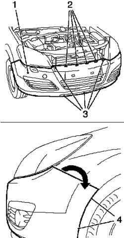
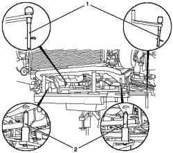
Fig. 2.107. Removing the bumper:
1 - bumper, 2 - clamps, 3 - rivets, 4 bolts fastening
Remove the bumper (see Figure 2.107) removing the 5 rivets and unscrewing 4 fixing screws (two on each side). Pull the front cover up in the direction of the arrow and move out from the bracket. Remove the front paneling, removing the 4 times. Remove the external temperature sensor. Remove the right engine splash guard.
Disconnecting the levers and pivots chassis
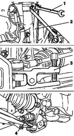
Fig. 2.108. Disconnecting the
levers and pivots chassis: 1 Wrench, 2 - lever pipe support rack springs, 3 - a special device KM507-C; 4 - steering knuckle joints
Loosen the two nuts and disconnect the lever from the pipe rack support springs (Fig. 2.108).
NOTE For holding the pipes, use the wrench.
Disconnect the steering traction from steering knuckle using a special device KM-507-C (Fig. 2.108). Remove the hinges from the steering knuckle, unscrewing the two nuts and removing the two screws. Extend bolt steering knuckle using special tool KM 915. Remove the hinges from the steering knuckle. Remove the rolls from the wheel hub otvernv 2 nuts.
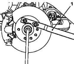
Fig. 2.109. Removing the shaft
hub: 1 - a special device
Hold the wheel hub with a special device KM-468-B (Fig. 2.109).
Drain coolant
Raise the car in half. Drain the coolant. To do this, place the bottom of the container for collecting liquid. Attach a suitable hose to the drain fitting.
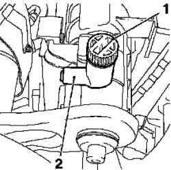
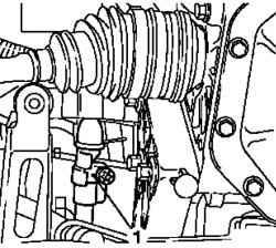
Fig. 2.110. Discharge connections
are: 1 - discharge screw 2 schtutser
Loosen the drain screw coolant (Fig. 2.110). After discharge tighten the drain screw coolant.
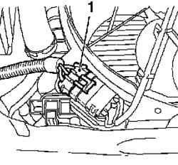
Fig. 2.111. Wiring harness
connector module cooling: 1 connector
Disconnect the wiring harness connector module cooling (Fig. 2.111).
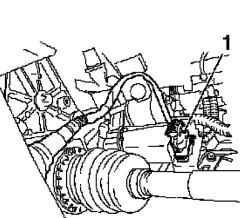
Fig. 2.112. Connector wiring
harness of oxygen sensor catalytic converter: 1 - connector
Disconnect the wiring harness of oxygen sensor catalytic converter (see Figure 2.112).
Remove the clamp draft gear. Loosen the mounting bolt and remove the steering deflector (Fig. 2.113).
Removing the components of the exhaust system
Fig. 2.114. Terminal silencer: 1 -
silencer, 2 - rubber bearing 3 clamp
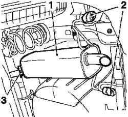
Remove the endpoint silencer (Fig. 2.114). Loosen the clamp mounting, unscrew the nut fastening. Remove the muffler from the bracket. Disconnect the two rubber feet. Remove the endpoint from the front muffler muffler.
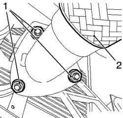
Fig. 2.115. Front exhaust pipe: 1 -
nuts, 2 - Exhaust
Disconnect the front exhaust pipe from the catalytic converter 3 unscrewing nuts (Fig. 2.115).

Remove the front exhaust pipe from the front muffler, disconnect the two rubber supports (see Figure 2.116).
Installing the front axle support
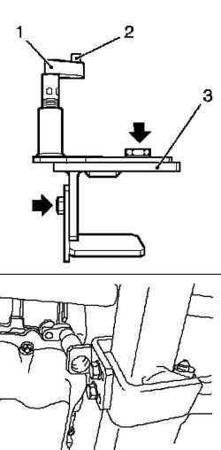
Fig. 2.117. Installation support the
front axle: 1 - prop, 2 - neck, 3 - a special device
Insert special device KM-6173 (Fig. 2.117). Loosen the 4 bolts (arrows) and tighten by hand. Align special device KM-6173 with the shell of the front axle. Enter your support. The neck of this should be a fixture on the engine block. Tighten the 4 bolts.
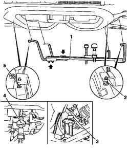
Fig. 2.118. Installation of a special
device KM-6001-A on the housing front axle: 1 - a special device, 2, 5 neck, 3 - rear support 4 - front support
Attach the KM-6001-A as shown in Fig. 2.118.
NOTE Using the KM-6001-A ensures alignment with the drive housing the front axle.
Loosen the 3 bolts (arrows) in the adjustment tires. Insert special device KM-6001-A. Necks should be in the holes to the front axle housing. Tighten the 3 bolts fastening the adjustment in the tires. Adjust the support and lift them to the constraints on the neck guides.
NOTE Necks should be in the supports gapless.
Disconnecting the hoses of the cooling system and damping bearings Lower the car.
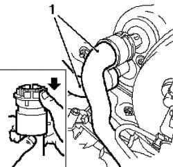
Fig. 2.119. Disconnecting the
hoses of the cooling system: 1 Hoses
Disconnect the coolant hoses from the radiator heater (Fig. 2.119).
NOTE Pre-apply for their tags
Place the bottom of the container for collecting liquid. Disconnect the 2 quick-coupling in the direction of the arrow. Pull the hoses coolant. Disconnect the right engine damping block bracket on the block.
Disconnect the left engine damping block bracket from the block (Fig. 2.120).
Fixing the front axle on jack
Raise the car completely. Attach a special device KM 904 and KM 6390. Connect to the hydraulic lifter.
NOTE Use a hydraulic jack, which can be dropped to a height of at least 100 cm
Fig. 2.121. Fixing the front axle on
jack: 1, 2 - pins
Vybeyte pins (see Figure 2.121). Remove the two pins. Podoprite housing front axle, make sure the reliability of support.
Pins must enter the corresponding holes in the hull of the front axle.
Removing the body of the front axle
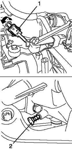
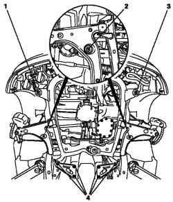
Fig. 2.123. Blocking draft gear: 1 -
draft gear, 2 - locking pin
Remove the front axle housing by unscrewing 10 screws (1, 2, 3, 4) (Fig. 2.123).
NOTE Not be disassembled body of the front axle of a shock pulse or a screwdriver.
NOTE Bolts are different lengths.
Setting
Check the thread. Check ease of movement of 10 mounting screws, replace them if necessary. Block draft gear. Turn the traction gear in the direction of the arrow.
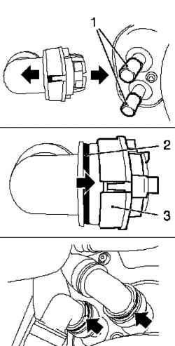
Fig. 2.124. Connecting the hoses
of the cooling system: 1 - socket radiator heater, 2 - clamps, 3 locking mechanism
At the same time press on the locking pin (Fig. 2.124). Replace the front axle housing.
NOTE Not be disassembled body of the front axle of a shock pulse or a screwdriver.
Install the front axle housing
Install the front axle housing. Use with new bolts. Tighten the screws 10 force 90 N * m, and then Dauvergne at +45 ° and +15 °. Remove the special adaptations KM 904 and KM 6390. Lower the hydraulic jack. Lower the car completely. Install the right damping motor unit to the adapter block. Tighten the 3 bolts are 55 Nm Install the left engine damping block to the adapter block. Tighten the 3 bolts are 55 Nm
NOTICE Be sure to follow the following order of assembly.
Connecting hoses of the cooling system
Connect the hoses to the radiator cooling system heater (Fig. 2.124). Move the two locking mechanism of quick couplings in the direction of the arrow until it stops. Plastic (green) rings at the same will be closed. Put two quick couplings for connecting pipes of the radiator heater until it stops.
NOTE Note the color marking
Move the two locking mechanism of quick couplings in the direction of the arrow until it stops (Fig. 2.124). Plastic (green) rings at the same will be closed. Ensure that quick release couplings are correct, and plastic rings (arrows) are visible. Raise the car in half. Set shafts of the wheels into the wheel hub. Insert the hinge in the steering knuckle. Tighten the two nuts moment 150 Nm, loosen the nuts at 45 °, and then tighten the moment of 250 Nm Use new nut. Hold the wheel hub with a special device KM-468-B. Set joint to steering knuckle. Use new nut. Tighten the two pivot point 50 Nm Attach the steering pull to the steering knuckle. Use new nut. Tighten the two nuts moment 30 Nm, then Dauvergne at +90 °, and then another +15 °. Install the lever on the pipe rack supports the suspension. Tighten the two nuts moment 65 Nm Use new nut. Use a wrench to keep from turning. Raise the car in half. Remove the special device KM 6173. Remove the two screws. Remove special device KM-6001-A. Remove the three screws. Install the front exhaust pipe from the front muffler. Install two rubber feet. Attach the front exhaust pipe with a front muffler to catalytic converter. Use a new gasket.
NOTE Use new nut.
Tighten the three screws moment 20 Nm Install rear silencer. Attach the rear silencer with a front muffler. Install two rubber supports and tighten the nuts. Connect the wiring harness of oxygen sensor catalytic converter. Connect the wiring harness connector module cooling. Install the right engine splash guard, tighten the 4 bolts fastening and fixed 2 rivets. Install drain bolt in the oil pan, using a new sealing ring. Tighten the drain bolt moment 10 Nm Replace the front paneling. Insert the panel plating in the bracket. Fasten outdoor sensor. Set 5 rivets. Tighten the 4 bolts. Install grille, fixing it in front of the casing. Set 4 rivets. Install the front wheel and tighten the 8 bolts fastening point 110 Nm Lower the car. Attach the delivery pipeline.
Connecting
Connect the wiring harness of steering control.
Connect the positive wire to the fuse holder and secure it nut. Install the wiring harness connector steering, secure it and styan wire clamps. Fasten all three terminals. Replace the cover fuse block. Install expansion tank coolant in the bracket. Connect the wire to the conclusion that a massive weight. Connect the positive wire to the positive terminal, and tighten the attachment bolt. Connect the wiring harness of the engine. Connect the wiring harness to the engine control module and wiring harness to secure it. Connect the wiring harness connector to the switch reverse. Connect the wiring harnesses of the engine. Connect the brake booster vacuum line to the intake manifold. Connect the fuel line feeding to the fuel rail. Connect the vent hose to the valve of the fuel tank.
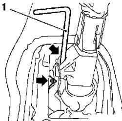
Fig. 2.125. Install the locking
mechanism of the gear lever: 1 fixing mechanism
Set fixing mechanism the gear lever, KM-527-A in case the gear lever (Fig. 2.125). Remove the lid from a central console. Remove the gear lever from the central console by unscrewing the two screws fastening. Raise the car completely. Install clamp rail for traction gear. Tighten the bolt fastening point 12 Nm Dauvergne it to +180 ° - 225 °. Lower the car completely. Remove air from the cylinder clutch. Replace the battery holder. Replace the air filter housing on the wheel arch and tighten the bolts. Connect the air intake hose to the throttle module and secure it ring. Connect the vent hose to the engine air intake hose. Connect the wiring harness to the sensor mass air flow. Fix the holder in the line of ventilation of the fuel tank. Replace the battery pack. Tighten the bolt, the intermediate steering shaft moment 22 Nm Cover the screw sealer to the threads (red) and wrap it. Remove the lock gear.
NOTE Locking pin in the hole this aiming automatically nominated when you first start reverse gears
Remove the special tool KM-527-A of the body gear. Replace the cover gear lever on the center console. Check the action of the gear lever. Check the ease of gear when parked car, engine running and the clutch is off. Fill the cooling system with liquid and remove it from the air. Program temporary memory. Close the hood.


