
Applies to Articulated Haulers
ST - New VOCOM2 interface for TechTool/MATRIS
NOTE!
Read and understand the safety instructions in the Operator's Manual and Service Information for the machine.
This Service Tip is to be considered as technical information only and is solely applicable for normal warranty in case of breakdown. Proactive replacement parts are not considered to be normal warranty.
A Service Tip gives a possible solution to a minor issue or other useful information. The information can be changed without notice.
Cause
New TechTool/MATRIS interface VOCOM2 88894000 cannot be used with Articulated Haulers. It is not possible to program the control units using this interface, as it will cause programming failures. There are also issues when communicating with the control units, which will cause interruptions in test, calibration, and operations. Diagnostic readings may not be complete.
NOTE!
VOCOM2 interface 88894000 is also included inTechTool kits 17279144 and 17279159.
Action
Do not use TechTool interface 88894000 when connecting to an Articulated Hauler. Use the older TechTool/MATRIS interface 88890300 or 88890020 to avoid time-consuming issues.
CLICK HERE TO DOWNLOAD THE COMPLETE MANUAL
• Thank you very much for reading the preview of the manual.
• You can download the complete manual from: www.heydownloads.com by clicking the link below

• Please note: If there is no response to CLICKING the link, please download this PDF first and then click on it.
CLICK HERE TO DOWNLOAD THE
Applies to
860 Volvo BM, 861 Volvo BM, 5350 Volvo BM, 5350B Volvo BM,A20 Volvo BM,A20C Volvo,A20C Volvo BM, A25 Volvo BM,A25B 4x4 Volvo BM,A25C Volvo,A25C Volvo BM,A30 Volvo BM,A30C Volvo,A30C Volvo BM,A35 Volvo BM,A35CVolvo,A35C Volvo BM,A35D Volvo,A40 Volvo,A40 Volvo BM,A40D Volvo
Claim routines

WARNING
Please pay attention to the safety instructions in the Operator's and Service Manuals concerned. Regarding: General
Supersedes SBA-000-K10 dated 3.83
When repairing or changing axles, transmissions, pumps, valves etc, the type number, manufacturing serial number or "Component Identification Number" must always be given on the claim form, otherwise the claim will not be approved.
The following examples show how the nameplates for type designation, serial number or "Component Identification Number" respectively are formulated.
The nameplates on components from other sub-contractors follow the same pattern.
VME IndustriesAB components:
1 Earlier type nameplates.
Here the description and manufacturing serial number of the component are given, e.g.AxleAH40, serial no. 1651.

1
2 Later type nameplates, see also SB G-000-75. Here the identification number of the component is given, which is a combination of the product number and consecutive number.
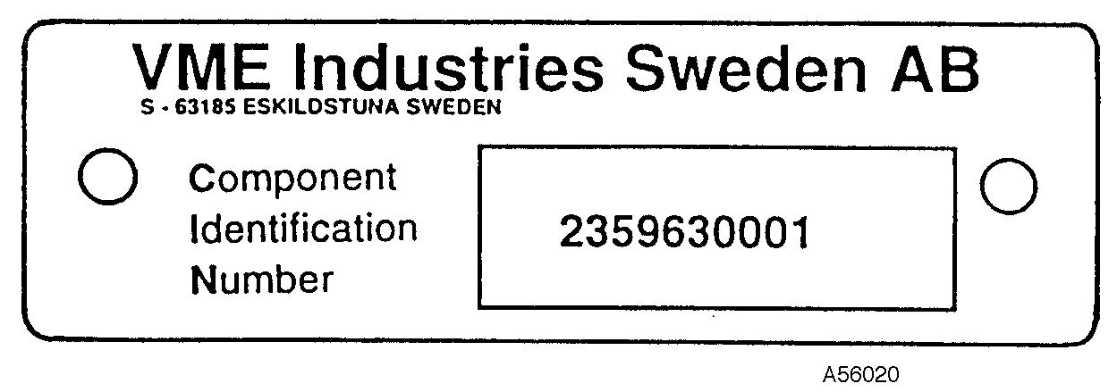
Figure 2
ELBAU,APS control unit.
Here the part number and series number are given, e.g: Part no. (Type) 11042014. Series no. 90271469
Figure
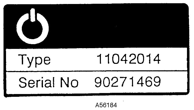
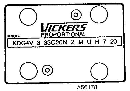
Figure 3
Vickers SystemAB components.
Here all numbers are given on the nameplate. The figure shows an example of a hydraulic valve where the Vickers model designation is indicated on the nameplate.
(On hydraulic pumps the identification is sometimes stamped directly in the material, in which case there is no nameplate).
4
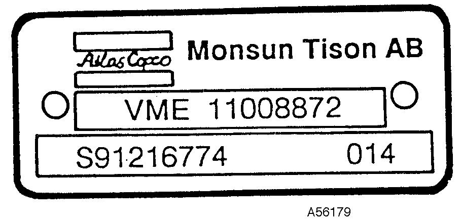
MONSUN-TISON HydraulikAB components.
Here all numbers are given on the nameplate.The figure shows an example of a hydraulic valve where the nameplate shows:
¡ ¡
The VME part number.
The Monsun-Tison part and code numbers.
(Other components such as electrical parts can have different number combinations).
5
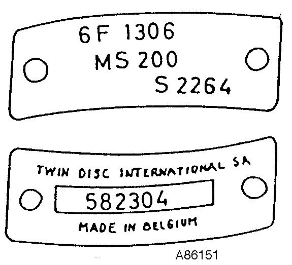
TWIN DISC torque converters
Here the information given on both nameplates can be found, e.g:
Type 6 F 1306 S 2264 MS 200
Serial no. 582304
Figure
Figure
6
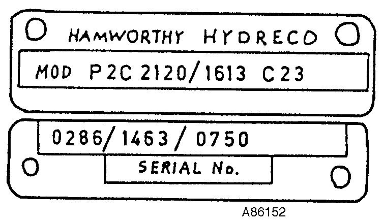
HAMWORTHYHYDRECO components
Here the information given on both nameplates can be found, e.g:
Model P2C 2120/1613 C 23
Serial No. 0286/1463/0750
Supersedes page 3/3 dated 01.92
7
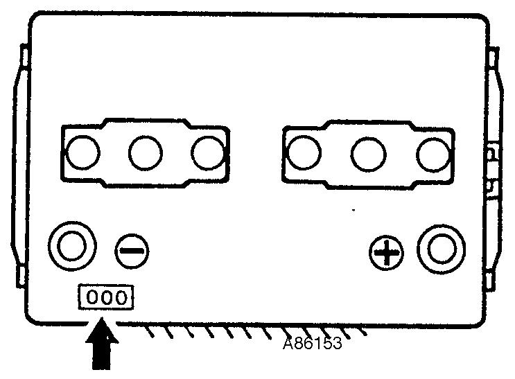
All plastic batteries are marked on the negative terminal (–). See position as shown in the figures. The marking can appear as follows: TA461.

Figure
Figure
Figure 8
CLICK HERE TO DOWNLOAD THE COMPLETE MANUAL
• Thank you very much for reading the preview of the manual.
• You can download the complete manual from: www.heydownloads.com by clicking the link below
• Please note: If there is no response to CLICKING the link, please download this PDF first and then click on it.
CLICK HERE TO DOWNLOAD THE
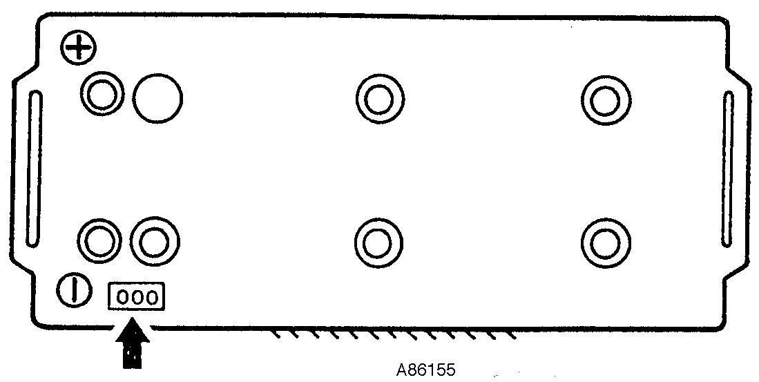
Figure 10
CLICK HERE TO DOWNLOAD THE COMPLETE MANUAL
• Thank you very much for reading the preview of the manual.
• You can download the complete manual from: www.heydownloads.com by clicking the link below
• Please note: If there is no response to CLICKING the link, please download this PDF first and then click on it.
CLICK HERE TO DOWNLOAD THE
Applies to
860 Volvo BM, 861 Volvo BM, 5350 Volvo BM, 5350B Volvo BM,A20 Volvo BM,A20C Volvo,A20C Volvo BM, A25 Volvo BM,A25B 4x4 Volvo BM,A25C Volvo,A25C Volvo BM,A30 Volvo BM,A30C Volvo,A30C Volvo BM,A35 Volvo BM,A35CVolvo,A35C Volvo BM,A35D Volvo,A40 Volvo,A40 Volvo BM,A40D Volvo
Action for reducing risk of fire
WARNING
Please pay attention to the safety instructions in the Operator's and Service Manuals concerned.
Regarding: General
It frequently happens that construction machines work in environments where inflammable material collects on the machines. Machine fires can be caused by different reasons, such as:
¡ ¡
Heating up through the exhaust system
Sparking in the electrical system
To reduce the risk of fire, check the following points when carrying out maintenance work on the machine.
General
It is important that the machine is provided with suitable equipment to reduce the risk of inflammable material collecting on the machine in its working environment and then catching fire.
Examples of such equipment for Volvo BM wheel loaders are:
¡ ¡ ¡
¡ Guard over silencer.
Protective gauze for radiator to prevent collection and blockage by wood chips, sawdust and similar.
Cyclone pre-cleaner of turbo type to increase the cleaning capacity, particularly against coarse dust, sawdust, wood chips etc. This is self-emptying and is not connected to the ejector connection on the exhaust pipe. This connection is plugged, meaning that the spark extinguishing function of the silincer is still effective.
Keep the machine and equipment free from dirt, waste material, fuel and oil spillage.
Instruct the machine owner to keep the machine clean at all times.
NOTE!
If high-pressure washing is used for cleaning, take care not to damage the insulation on the electric leads, which can happen even at a relatively low water pressure and temperature.
Engine
Clean off all rubbish from the engine, particularly around the exhaust system, turbocharger and alternator.
¡ ¡ Check that there is no fuel or oil leakage and that the hoses are clamped in such a way that no chafing occurs.
Fuel filling.
Take care when filling up with fuel that none is spilt outside the filling pipe.
Fuel mixed with dust and rubbish is a significant cause of fire.
If fuel has run out when filling up, wipe it up immediately.
Do not fill upp with fuel near an open fire.
Electrical system
¡ ¡
If the machines is left unattended, always turn off the battery disconnection switch.
Check the electric leads for abrasion and that they are not subjected to wear.This particularly applies to unfused leads, which are red and marked R (B+).
E. g., leads between:
¡ ¡ ¡ ¡ Batteries
Battery and starter motor
Alternator and starter motor
Lead to engine starter element
In cases where these leads have been disconnected it is important to make sure that they are fitted and clamped in such a way that there is no risk of abrasion. Unfused leads must not come into contact with oil or fuel hoses.
When fitting any extra equipment, make sure that all leads are fused and arranged and clamped in such a way that there is no risk of abrasion.
¡ ¡ Clean off all rubbish.
Check that there is no oil leakage.
Brake system (hydraulic)
¡ Check that there is no oil leakage and that pipes and hoses are protected, undamaged and properly clamped.
Protecting plates (bottom guard plates)
On machines such as compactors which are provided with bottom guard plates it is important that rubbish which has collected inside and on the plates is removed every day.
The guard plates must be handled with care as they are very heavy. Instructions for correct handling of the plates can be found in the instruction book or supplement for the respective machine.
Hydraulic system
Check that threre is no leakage.
Welding
Take great care when carrying out welding work on the machine. Make sure that fire extinguishing equipment is available. Take particular care when welding close to fuel and oil lines and tanks.
If fire breaks out
At the slightest sign of fire, and if the situations permits, take the following action:
Drive the machine away from the hazardous area
Let down the lifting arms, dumper body etc to bottom position
Stop the engine with the stop control and turn the key switch to "O"-position
Get out of the cab
Turn off the main current with the battery disconnection switch
Start fire extinguishing work and alert the fire service if necessary
In connection with delivery instructions or at other service visits, please inform the owner/driver of the contents of this Service Bulletin.
Applies to 860 Volvo BM, 861 Volvo BM, 5350 Volvo BM, 5350B Volvo BM,A20 Volvo BM,A20C Volvo,A20C Volvo BM, A25 Volvo BM,A25B 4x4 Volvo BM,A25C Volvo,A25C Volvo BM,A30 Volvo BM,A30C Volvo,A30C Volvo BM,A35 Volvo BM,A35CVolvo,A35C Volvo BM,A35D Volvo,A40 Volvo,A40 Volvo BM,A40D Volvo
New warranty routines for Bosch diesel equipment
Regarding: General
WARNING
Please pay attention to the safety instructions in the Operator's and Service Manuals concerned.
For the more effective processing of warranty and claims routines with regard to Bosch diesel equipment, Bosch and the VCEcompaniesART, EXC and WLO have reached an agreement on warranty matters covering ordinary warranty time. The agreement applies with effect from 970101. This means that, in future, these warranty matters will be handled according to one of the following routines.
Alternative 1:
Simpler faults of such a kind that the VCE dealer or Bosch representative can remedy it. Where the entire work is done by the VCE dealer, the costs involved will be settled by sending a claim to the VCE-company concerned.
In those cases where the Bosch representative does the whole job, the Bosch representative will bear the entire cost. Examples of simpler faults: Replacing a feed pump, replacing nozzles or changing a pump shaft seal.
Alternative 2:
Bigger faults of such a kind that the VCE dealer lets the Bosch representative repair the fault. Bosch pays for the repair costs, while removal and fitting costs are settled via a claim against the VCE-company concerned. Example:The fault is of such a kind that, after repairs, the injection pump has to be run on a test bench.
Alternative 3:
With bigger faults of such a kind that the VCE-dealer decides that the component in question must be replaced by an exchange component, the component is ordered according to standard routines. Any claims demands are to be made to be VCE-company concerned. Example: It has been established that an injection pump cannot be repaired, or it cannot be repaired within a reasonable time. When a claim has been sent to a VCE-company, it shall state three groups of digits: Code for manufacturing date, serial number, and the Bosch part number, Fig.
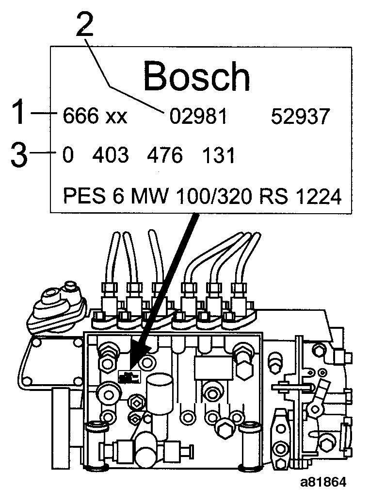
Figure 1
Example of identification plate