2 minute read
Replacing the fuel line pressure (High pressure pump - pressure chamber


Tighten the 4 nuts moment 25 Nm Attach masloproovod. Connect 4 oil line to the fuel injectors.
NOTICE When tightening the locking nut holding the fuel injectors open wrench. Flow line can only be connected only once.
Install 4 new high pressure pipeline. 4 Tighten the lock nut (M12) moment 25 Nm 4 Tighten the lock nut (M14) moment 23 Nm Connect the battery pack. Attach the grounding connector to the grounding terminal. Tighten the nut. Check the tightness of the fuel system.
NOTICE Before checking wear goggles and protective gloves.
Start the engine. Replace the cover of the engine. Program volatile memory. Close the hood.
NOTICE When working with system «Common Rail» wait for one minute after the engine stops. The system automatically resets the pressure.
NOTICE When you work with observe the cleanliness of the fuel, since even very small particles of dirt can cause problems in the engine or system. Close an open socket of the fuel system with suitable plugs. Reapply placeholders are not allowed.
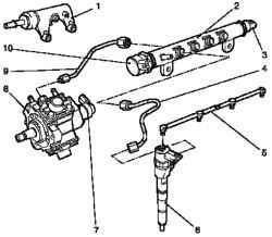
Fig. 2.270. The components of the
fuel system «Common Rail»: 1 damp housing, fuel return, 2 - highpressure chamber, 3 - pressure sensor, 4 - a pipeline of high pressure (pressure chamber to the fuel injector), 5 - oil line 6 - the fuel injector, 7 - high pressure pump, 8pressure regulator, high pressure pump, 9 - pressure regulator, pressure regulator, 10 - line of high pressure (high pressure pump to a pressure chamber)
Withdrawal
Open the hood. Disconnect the battery. Disconnect the grounding connector on the grounding clamp. Remove the engine Remove the inlet pipe. 3 Disconnect the wiring harness.
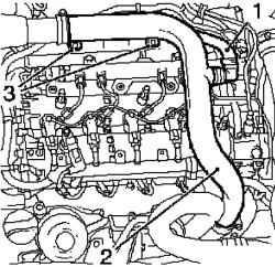
Fig. 2.271. Removing the inlet pipe
and ventilation hose Engine: 1 ventilation hose Engine, 2 - inlet pipe, 3 - bolts fastening
Disconnect the vent hose, the engine (Fig. 2.271). Disconnect the quick release coupling. Disconnect the air intake hose from the turbocharger. Loosen the clamp. Disconnect the hose from the air intake, mass air flow sensor. Loosen the clamp and unscrew the 2 screws fastening. Place the bottom of the container for drainage.
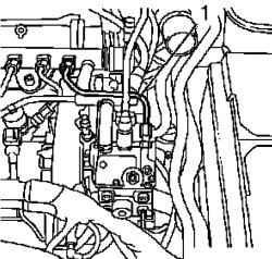
Fig. 2.272. Removing the high
pressure pipeline: 1 - Pipeline
Disconnect the high pressure pipeline from the high pressure pump to the pressure chamber. 2 Loosen the coupling nut. (Fig. 2.272).
Setting
Install high pressure pipeline from the high pressure pump to the pressure chamber. Use the new high pressure pipeline. Tighten the coupling nut M14 moment 19 Nm Tighten the coupling nut M12 moment 24 Nm Install inlet pipe. Attach the hose to the inlet turbocharger. Tighten the clamp point 3.5 Nm Attach the sensor mass air flow to the air intake hose. Tighten the clamp point 3.5 Nm Attach the vent hose engine. Fasten the clamp. Tighten the 2 screws fastening. Attach the wiring harness 3. Replace the cover of the engine. Connect the battery pack. Attach the grounding connector to the grounding terminal. Tighten the nuts. Program volatile memory. Close the hood.


