5 minute read
The main brake cylinder


1. Using a steel brush, remove the pipe cover the length of 6,5 mm from the end, which will be laminated. 2. Clamp the brake lines to adjust for the 5 mm brake lines. 3. Use a tool for expanding (E or F) for the brake lines with a diameter 4,75 mm. Expanding the type F - I. Capture (Workholding, 5 mm). Brake line with expanding type F. Tool for expanding the type F (4,75 mm). Expanding the type E - II. Capture (Workholding, 5 mm). Tool for expanding the type E (4.75 mm). Brake lines with expanding the type E.
Brakes new master cylinder and new brake booster
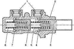
Fig. 6.2. General view of the
tandem master brake cylinder: 1 socket compensating reservoir, 2 building a tandem master brake cylinder type, and 3 - the primary piston (piston pusher), 4 - sealing sleeve of the primary circuit; 5 compression springs, 6 - secondary piston (floating piston ) 7 - sealing sleeve in the secondary circuit, 8return spring
Restrictions on the size marker in all models of Astra-H engine Z19DTH and Zafira to the left-hand steering led to the need to design new, more compact master brake cylinder. Effect of this tandem cylinder based on the principle of "plunger".
Unlike conventional master brake cylinder, sealing plugs are embedded in the body instead of being installed on the piston, as before. The hole in the hull, thus directly sends pistons. This design reduces the length of the tandem master brake cylinder by 25%. In addition, the number of nodes is reduced to 15, thus significantly lowered weight, reduced size and length of service.
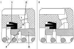
Fig. 6.3. The scheme of the master
brake cylinder in a free state and after a free running: I - tandem master cylinder in a free state; II Tandem master cylinder after free running; 1 - sleeve sealing 2 - ring groove 3 - primary or secondary piston; 4 - hole in the piston
"Plunger" tandem master cylinder like the 2nd generation, like almost all the brake cylinders, provides the dual-circuit brake system. Contours of pressure are consistent. Force the driver is passed as usual, from the stock brake booster to the primary pistons. Creates a preliminary pressure of compression springs mounted on the end of the primary piston, and it provides a virtually simultaneous transfer efforts to the secondary piston (floating piston). Joint action of two pistons in one spring would reduce the free running and causes the secondary braking circuit to react more readily than it does in conventional tandem master cylinder.
In the system used to date the secondary piston is driven by the pressure in the primary circuit brake system. This leads to an increase in free running, because at first the pressure should increase up to 437
a specified level. Second compression spring is located behind the secondary piston is returnable. It must be tough enough to ensure that the overcoming of friction sealing sleeves, but at the same time soft enough to protect the ability to compress under the action of the spring the first circuit when the brakes are activated. Initially there is depressurized the connection between the master brake cylinder, a tandem type and Countervailing reservoir. This provides pressure compensation and productivity in the brake system. When the brake is actuated cylinder piston includes a sealing sleeve, after a short free running. Connect with encapsulated compensation reservoir ceases. Once the rubber sealing elements provided, the amount of brake fluid begins to move and brake system is under pressure. Once the brake is released, return spring attaches pistons back to recovery to seal the connection between the tandem brake master cylinder reservoir and compensation. In cars equipped with an ESP and Traction Control performance brake system in case of intervention by the system should be provided with additional supply. Since the time for the working mode of the pump ABS depends on the resistance in the suction system, the cross section of holes and channels should be as much as possible. In the case of intervention traction control system proivzoditelnost braking system is provided by an annular groove, which is located opposite the holes in the piston, when the master cylinder is in a free state. When the brakes are included in the work in the regulatory process, the additional brake fluid, which was filed with the brakes traction control system, comes back to the relief tank pressure. The degree of pressure increase on the return is determined by the instantaneous performance braking system and the pressure in the brake system, which was established traction control system. If, when you use the brakes, the control system moves from traction control to harness the anti-lock braking system, compensating the hole can open up the pressure in the main brake cylinder as a result of the need to return the brake fluid in the master cylinder during the phase of pressure decrease in the anti-lock braking system. Pressure relief tank in the outflow depends on the pressure in the main cylinder, which is operated by the driver. The quantity of liquid that flows back into the reservoir at this time, depends essentially on the performance of the braking system and the current control settings. The combination of stress, overflow and output during operation of the brakes is possible, as the state of the system.
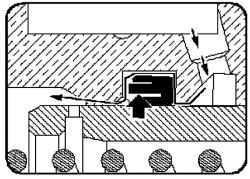
Fig. 6.4. Primary bush master
brake cylinder tandem type
Primary bush master brake cylinder tandem type remains under pressure created by excess capacity in the brake circuit, until not reached final position.
Inner projection of the primary hub is under pressure and on the outside and from the piston to compensate for the total pressure on the sleeve. This prevents damage to the sleeve edges (sealing edge) at the exit of the piston to limit, as happens in the main brake cylinder tandem type with Vent hole where there is a drop in pressure in the bush. In principle, the change due to reverse filling (decrease in productivity at constant pressure) is the same as the change when you release the pedal (pressure decrease with a decrease in performance) because edge sleeve is in contact with the piston with a decrease in productivity. In the case of the system ESP, however, brake fluid should also be made whenever the master cylinder is activated. In this case the pump antilock braking system applies additional brake fluid from the compensation tank. Then the brake fluid passes through the primary hub, causing folding sealing protrusion, while between the piston and the hole created by the annular gap. Brake fluid can now get the pitcher to the corresponding socket. Arrows - current direction of brake fluid. Arrow provisions - outer edge of the sealing sleeve is bent inwards.


