10 minute read
Removing and installing the rear cover gearbox (F 13


Remove the back cover (Figure 3.53). Remove the cover gasket.
NOTE If necessary, loosen the fastening lid light strikes a rubber hammer. NOTE Drain the gear oil.
Disconnect the special device KM 6155. Remove the differential. Remove the working cylinder clutch. Remove the discharge pipe and discharge pipe mounting sleeve. Remove the main bearing and the shaft of the transmission housing. Remove the 2 sealing rings of the shaft wheel. Remove the transmission housing through a special device KM 6115.
Setting
Attach the new transmission housing to the special adaptation of the CM 6115. Install the main bearings and shaft. Install differential. Install discharge pipe and discharge pipe mounting sleeve. Install working cylinder clutch. Attach a special device KM-6155 to the gearbox. Replace the back cover.
NOTE Pay attention to the magnet. NOTE Note the similarity of the bolts.
Attach the rear cover. Replace it with a new gasket on the transmission housing. Tighten the 4 bolts M7 moment 15 Nm Tighten the 5-bolt M8 moment 20 Nm Replace the cover gearbox. Set switch reversing lamps. Tighten the switch reversing lamps moment 20 Nm
NOTE Use new O-ring.
Install 2-wheel shaft sealing ring. Install the left engine damping block Tighten the 3 bolts fastening point 55 Nm
NOTE Work is being carried on the established transmission.
Withdrawal
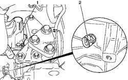
Fig. 3.54. Removing the gearbox: 1
- cover 2 - switch reversing lamps
Remove the gearbox and switch reversing lamps (Figure 3.54). Disconnect the wiring harness connector, switch reversing lamps. Unscrew the switch reversing lamps Remove the casing front axle.
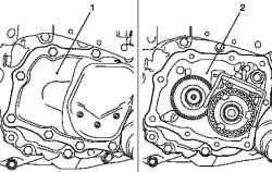
Remove the back cover by unscrewing the mounting bolts 9 (see Figure 3.55).
NOTE If necessary, loosen the fastening lid light strikes a rubber hammer.
Remove the rear cover gasket.
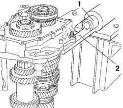
Fig. 3.56. Installation of special
devices: 1, 2 - devices
Attach the back cover of a special adaptation of KM 552 (Fig. 3.56). Attach the back cover of a special adaptation of KM-113-2 using a special device KM-552.
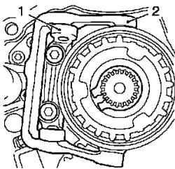
Fig. 3.57. Withdrawal of support
bearing with a yoke with the back cover: 1 - a support bearing 2 rocker
Remove the support bearing with the yoke with the back cover (Figure 3.57).
NOTE If the mounting bolts do not turn away, the back cover of a hair dryer heat to a temperature of about 80 ° C.
Unscrew the 2 screws fastening. Remove the fifth gear transmission (slave). Remove the retaining ring from the body synchronizer.
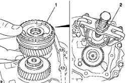
Fig. 3.58. Removing the gear
wheels, gear fifth gear and fifth gear synchronizer body with the main shaft: 1 - body synchronizer 2 adaptation
Remove the cog wheel, gear fifth gear and fifth gear synchronizer body with the main shaft with a special device KM-161-B (Figure 3.58). 2 Remove the needle bearing gear fifth gear.
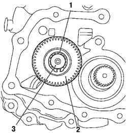
Fig. 3.59. Removing the gear from
shaft: 1 - Holder, 2 - fifth gear transmission, 3 - drive shaft
Remove the fifth gear transmission (lead) (2) of the shaft and remove the holder (Figure 3.59).
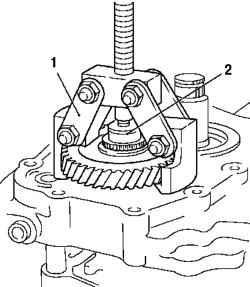
Fig. 3.60. Removing the gear with
the help of a special device: 1 - a special device, 2 - thrust bush
Remove the fifth gear wheel transmission, (lead) from the shaft using a special device KM-553-A (Figure 3.60).
NOTE Monitor the proper installation of special devices KM-553-A at the toothed wheel 5-th channel (lead).
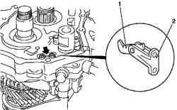
Fig. 3.61. Removing the support
bearing: 1 - Latch, 2 - bearing bearing
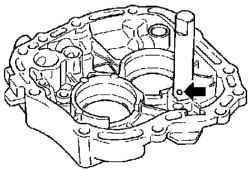
Disconnect the support bearing with a clip on the back cover (Figure 3.61). Unscrew the 2 screws (arrow in Figure 3.61).
NOTE If the mounting bolts do not turn away, the back cover of a hair dryer heat to a temperature of about 80 ° C.
Remove the plugs (arrows in Figure 3.62) from the back cover.
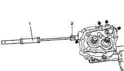
Fig. 3.62. Removal of plugs: 1, 2 -
a special tool
Remove the cap using a special tool for KM 727 and KM-328-B (Figure 3.62).
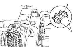
Fig. 3.63. Removing the bridge
clamping bolt back cover: 1 - Bridge 2 - bolts fixing
Disconnect the bridge clamping bolt rear cover by unscrewing 2 screws fastening (Figure 3.63).
NOTE The bridge can be removed if it included the 3rd transfer.
Turn 2-S transmission and 5-S transmission. Turn 2 transfers with the holder of the switch (arrows in Figure 3.63).
NOTE Reduce the pressure on the guide rod gear-changing - for this, support rods change gear on top a wooden block.
Remove the fork gear, 3rd / 4 th gear and reverse gear. Vybeyte cylindrical pins of the shift fork 3rd / 4 th gear and forks include reverse gears c using a special tool KM 308. Remove the core of the gear rod include reverse gears and fork gear.
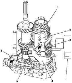
Fig. 3.64. Removing the
components of the switching mechanism of 5-th transmission: 1 wooden block, 2 - shaft gearchanging, 3 - plug switch 3 / 4 gears, 4 - switching mechanism 5-th transmission, 5 - splint, 6 - fork include reverse gears
Remove the shifter 5-th transmission with the rear cover (Figure 3.64). Remove the cotter pin and remove the cylinder latch the back cover.
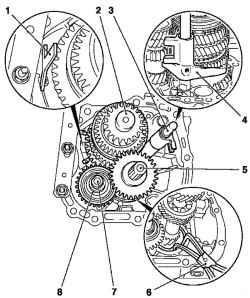
Fig. 3.65. Removing the
components of the switching mechanism of reverse gears: 1 plate 2 - retaining rings of the main shaft, 3 - gear shift fork rod 1 st / 2 nd, 4 - gear shifting fork 5 - a drive shaft; 6 - a special tool, 7 - axle gear reversing 8 - idler reverse
Remove the 2 retaining rings of the main shaft and drive shaft with a special tool KM-443-B (Figure 3.65).
NOTE When withdrawing, hold the retaining ring of the main shaft under tension corresponding to the plate (Figure 3.65).
Remove the main shaft from the rear cover. Remove the drive shaft from the rear cover. Remove the idler reverse of the back cover. Remove the fork gear shift and gear shift fork rod 1 st / 2 nd transmission of the back cover. Remove the axle gears reverse from the back cover. Clamp the rear axle pinion in a vise with copper sponges. Gently Destroy the back cover of a copper rod.
NOTE Note that holding the ball utaplivaetsya.
Clear all items and sealing surfaces. Check all items for damage.
Setting
Lubricate the rotating elements and contact surface of the liquid from the gearbox.
NOTE Pay attention to the loading position.
Zapressuyte axle gears in the rear of the rear cover.
Set fixing ball (arrow) (Figure 3.66). Zapressuyte axle gear reversing all the way Fig. 3.66. Fixing ball
NOTE Coat the bearing and the hole reverse transmission oil.
Install the main shaft in the bearing. Install drive shaft into the rear cover. Install reverse gear in the rear cover.
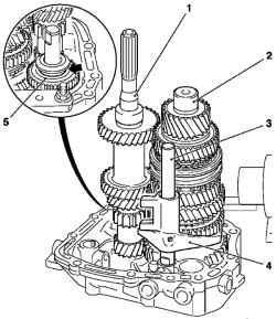
Fig. 3.67. Installing the gear
mechanism components: 1 - drive shaft, 2 - the main shaft, 3 - gear shift fork rod 1 st / 2 nd, 4 - gear shifting fork, 5 - reverse gear
Paz forks gear (arrow in Figure 3.67) reverse gear facing upwards. Insert fork gear shift rod with a 1 st / 2 nd gear in the rear cover. Install new retaining rings. Install snap rings with a special tool KM-443-B. Install tightening bolts, gears, reverse and 3-rd / 4 th transmission. Reduce the load on the guide rod gear in the back. When installing the pins podoprite rod gear wooden wedge. Install the plug shifting gears and reverse gear-changing stock. Install a cylindrical pin with a special tool KM-308.
Install the plug switch 1 st / 2 nd transfer and stock transfer switch. Install a cylindrical pin with the KM 308.
NOTE Protrusion of the new pin is approximately 2 mm / 0,08 (Size I).
Insert holder 5-th transmission. Install the gearshift fork and stem forks gear, 3rd / 4 th transmission. Install a cylindrical pin with the KM 308.
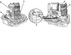
Fig. 3.68. Installation of
components switching mechanism 1 st / 2 nd Shows: 1 - clamping bolts 2 - stock transfer switch, 3 - plug switch 1 st / 2 nd transmission, 4 - a special tool, 5 - fork shifting gears reverse 6 - rod change gear
Set 4 Blank.
Drive in stoppers to stop nylon with a hammer or a soft metal rod. Slide the fork gear shift in neutral position. Turn 3 assists. Turn 2-S transmission.
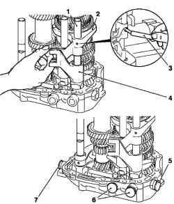
Fig. 3.69. Removing the
components of the switching mechanism of 5-th transmission: 1 gear shift fork rod 1 st / 2 nd 2 - gear shifting fork, 3 - a special tool, 4 holder of 5-th transmission, 5, 6,7 Stoppers
Turn on the 3rd gear.
Including 5-S transmission. Attach a bridge clamping bolt rear cover.
NOTE Cover the bolts fixing composition.
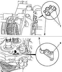
Fig. 3.70. Installation of the bridge:
1 - clamping bolts 2 - Bridge 3 Latch, 4 - bearing bearing
Slide the fork switch 1 st / 2 nd gear in neutral position.
Secure the 2 screws of the bridge point 7 Nm Slide the fork gear shift in neutral position. Secure the support bearing in the rear cover latch.
Tighten the 2 bolts moment 9 Nm Remove the back cover with the help of special devices KM 552 KM-113-2.
NOTE Long hub gear facing toward the back.
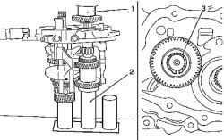
Fig. 3.71. Press-fit pinion 5-th
transmission: 1 - a special tool, 2 - a special tool, 3 - circlip
Press the pinion 5-th transmission (lead) on the driving shaft by means of KM 514 (Fig. 3.71). Replace the back cover from the main shaft and drive shaft in a special adaptation of the CM 554. Install a new circlip. Attach the rear cover to the KM-113-2 with a special tool KM-552.
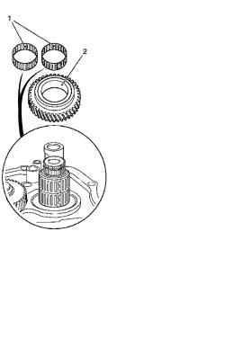
Fig. 3.72. Installing the gear 5-
second transfer to the main shaft: 1 - Pinion 2 - needle bearings
Install pinion 5-th transmission to the main shaft (Fig. 3.72). Cover 2 needle bearing transmission oil. Install 2 needle bearings on the main shaft.
NOTE Make sure the landing needle bearing.
Fig. 3.73. Installing the gear, gear
and fifth gear fifth gear synchronizer body with the main shaft: 1 - body synchronizer, 2 retainer ring, 3 - fifth gear transmission
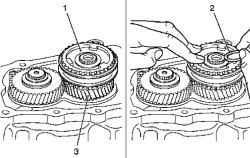
Install gear, fifth gear transmission, and building on the main synchronizer shaft (Fig. 3.73). Coat the bearing surface of the main shaft and housing synchronizer transmission oil. Install a new circlip.
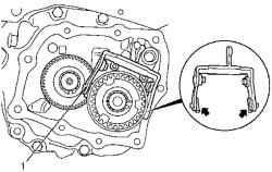
Fig. 3.74. Installing the shoe to
activate the plug-fifth transmission: 1 - body synchronizer
Replace shoe (arrows) on the fork inclusion fifth gear (Fig. 3.74). Attach the support bearing with a yoke to the back cover. Tighten the 2 new bolts moment 22 Nm
NOTE Install bolts with a fixing composition.
Set friction washer axle gears reverse.
NOTE Friction washer fix grease.
Check the position and placement of components listed below. Stock switch 3rd / 4 th gear. Fork shift 3rd / 4 th gear. The control for 5-th transmission. Stock switch 1 st / 2 nd gear. Fork switch 1 st / 2 nd gear. Pin restrictor inclusion transmission. Fork include reverse gears. Stock activate reverse gears. Replace the back cover.
NOTE Note the similarity of the bolts.
Attach the back cover with new gasket to the transmission housing. Tighten the 4 bolts M7 moment 15 Nm


