16 minute read
Removing and installing the crankshaft (engine 1.4 liters


Replace the spark plug threads in the cylinder number 2. Give compressed air into the cylinder number 2. Replace valve stem seals, cylinder number 2. Relocate adapter supply of compressed air. Shut off the supply line of compressed air. Unscrew the adapter from the spark plug threads, cylinder number 2. Replace the spark plug threads in the cylinder number 3. Give compressed air into the cylinder number 3. Replace valve stem seals, cylinder number 3. Shut off the supply line of compressed air. Detach lever valve springs. Remove the adapter compressed air. Loosen the crankshaft. Set the gearshift lever to neutral position. Turn off the parking brake systems. Raise the car. Lock the crankshaft. Pull the chain drive mechanism for timing up. Evenly, rotate the crankshaft until it stops a special device KM 952. Install special tool KM-952. Lower car
Setting
Replace spark plug with a special device KM-194-E and tighten the moment 25 Nm Visually check the elements - camshafts, camshaft bearing cap, cylinder head, valve tappets, hydraulic valve tappets. Install hydraulic lifters and tappets.
Withdrawal
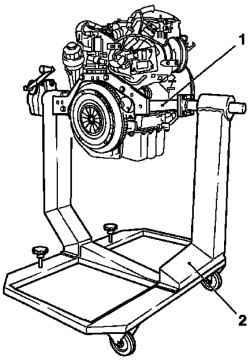
Remove the engine. Remove the manual transmission. Install the engine in a special fixture KM 412. Lift the engine. Set a special device KM-412-18 (1) on the engine. Tighten the 4 bolts fastening.
Fig. 2.176. The engine installation
on a special stocks: 1 - head, 2 biscuits
Secure the motor in the KM 412 (Fig. 2.176). 8 Tighten the mounting bolts. Remove the restraining ropes KM-2358.
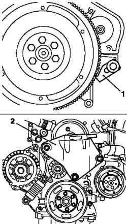
Fig. 2.177. Withdrawal of support
damping unit: 1 - a special device, 2 - bearing damping unit
Disconnect the support damping engine block from the housing valve gear / cylinder (Fig. 2.177). Loosen the 3 bolts. Remove the clutch. Place the bottom of the container for drainage, loosen the bolt holes drain and drain engine oil. Assemble the motor oil. Tighten the bolt holes drain with a new O-ring moment 10 Nm
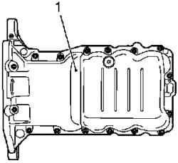
Fig. 2.178. Oil-pan: 1 - Palette
Remove the oil pan from the base of the cylinder block, turning away 16 mounting bolts (Fig. 2.178). Clear Poly-V belt. Check direction of rotation. Turn tensioner Poly-V belt (arrow in Figure 2.179), in a clockwise direction using a special tool KM 6131 Install special tool KM-955-2 and with his help loosen the tensioner Poly-V belt (Fig. 179). Clear Poly-V belt tensioner. To do this, turn the tensioner Poly-V belt in the direction of the arrows in Figure 2.180, using a special tool KM 613. Remove the special tool KM-955-2. Belt Poly Loosen tensioner, loosen the 2 bolts (arrows in Figure 2.180). 229

Remove the tensioner Poly-V belt (Fig. 2.180).
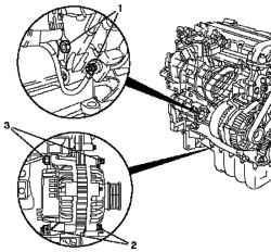
Fig. 2.181. Removal of the
alternator: 1 - nuts, 2, 3 - Bolting
Disconnect the alternator. To do this, disconnect the wiring harness of an alternator, loosen the 2 nuts, remove the 2 bolts and remove the alternator (see Figure 2.181). Remove the thermostat housing and coolant hose from the coolant pump, 3 unscrewing bolts. 3 Remove the clamp and disconnect the coolant hoses from the pump coolant. Disconnect connectors camshaft sensor wiring harnesses, oil pressure and coolant temperature.
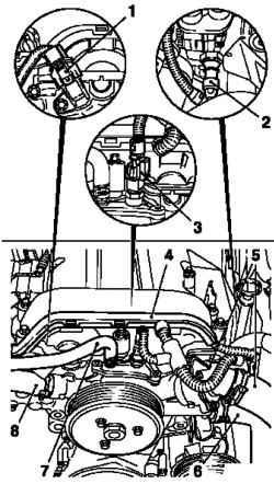
Fig. 2.182. Removing the coolant
hoses and wiring of sensors: 1 connectors wiring harnesses camshaft sensor, 2 - wiring harness connector of the oil pressure sensor, 3 - the wiring harness connector coolant temperature sensor, 4 - wiring harnesses, 5 coolant hose, 6, 7, 8 - coolant hoses
Disconnect the wiring harness from the lid of the cylinder head, and bring them back (Fig. 2.182). Fig. 2.183. Removing the belt
pulley pump coolant: 1 - pulley, 2 bolts fixing
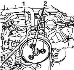
Remove the belt pulley coolant pump by unscrewing the bolt fastening 3 (Fig. 2.183). Mark the position of guide bushings, when removing the pump coolant.
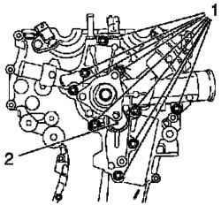
Fig. 2.184. Removing the pump
coolant: 1 - mounting screws, 2 pump coolant
NOTE Pump bolts are different lengths.
Disconnect the ventilation hose from the cover of the engine cylinder head Remove the wiring harness ignition module. Remove the ignition module with the lid of the cylinder head in the direction of the arrows in Figure 2.185. Loosen the two bolts.
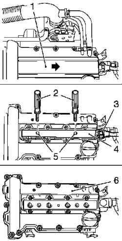
Fig. 2.185. Components shooting
in dismantling the ignition module: 1 - ignition module cover, 2 - a special tool; 3 - Ignition module wiring harness, 4 - ignition module 5 - mounting screws, 6 - cylinder head cover
Separate the ignition module from the spark plug with a special tool KM 6009 (Fig. 2.185). Remove the lid of the cylinder head from the cylinder head by unscrewing the mounting bolts 13. Rotate the crankshaft in the position of top dead center (TDC) of cylinder number 1 (ignition) in the direction of rotation of the engine. Check belt pulley on the crankshaft must sit in front of the projection on the case of the mechanism of timing.
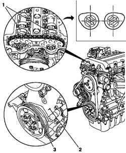
Fig. 2.186. Install the crankshaft
position at top dead center (TDC), piston cylinder number 1: 1 - cams cylinder number 1, 2 - lug 3 - Tag
In this position number 1 cylinder cams are located in front of TDC (the ignition) (both cam pointing outward) (Fig. 2.186). Remove the belt pulley of the crankshaft. Hold the hub of the crankshaft bolt, loosen the 6 bolts. Fig. 2.187. Removing the belt
pulley crankshaft: 1 - belt pulley, 2 wheel hub bolt crankshaft, 3 special tool
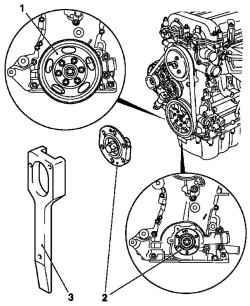
Loosen the bolt hub of the crankshaft (2) (do not remove it), hold a special tool KM 956 (Fig. 2.187). Loosen the bolt from the hole at the base of the cylinder block Lock the crankshaft. Install special tool KM-952 in the hole. Slowly turn the crankshaft bolt for the hub of the crankshaft in the direction of rotation of the engine, while a special tool KM-952 you hit a jumper in the crankshaft or the base of the cylinder block. Fig. 2.188. Поворачивание
коленчатого вала: 1 – болт; 2 –специальный инструмент; 3 –метка
Check on the hub of the crankshaft must be turned up in this position (Fig. 2.188). Fig. 2,189. Locking camshaft: 1 -
special tool
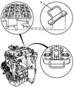
NOTE Special tools must be installed in the grooves of shaft until it stops.
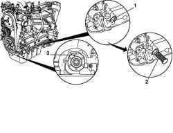
Remove the hub of the crankshaft and unscrewing bolts.
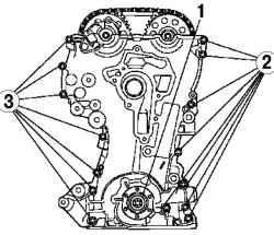
Fig. 2.190. Removing the hub of
the crankshaft: 1 - hub, 2, 3 - bolts fastening
Remove the casing valve timing mechanism by unscrewing bolts 15 (Fig. 2.190).
Removing the timing chain drive mechanism
Loosen the pulley bolts distribution shaft. Hold camshafts per hexahedron. Block chain tensioner. Install special tool KM-955-1. Slide back timing chain and lock it with a special tool KM-955-1. Remove the guide by unscrewing 2 screws fastening. Remove the guide by unscrewing 2 screws fastening. Remove the guide tension by unscrewing the bolt fastening.
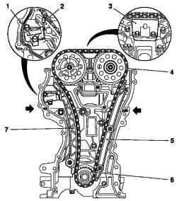
Fig. 2.191. Removing the timing
chain drive mechanism: 1 - timing chain, 2 - a special tool, 3 - slide 4 timing chain drive mechanism; 5 slide 6 - asterisk, 7 - directing tension
Remove the drive chain mechanism for timing, drive sprocket and the gasket body mechanism timing (Fig. 2.191). Disconnect the wiring harness connector pulse sensor crankshaft. Remove the special tool KM 952. Remove pulse generator crankshaft, unscrewing bolts.
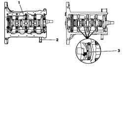
Fig. 2.192. Removing the
connecting rod: 1 - the base of the cylinder block, 2 - a special tool, and 3 - connecting rod bearing caps
Disconnect the base of the cylinder block of the cylinder block by unscrewing the bolt 22 fastening (Fig. 2.192). Remove the connecting rod bearing.
NOTE Surfaces of contact rods and connecting rod bearing caps are selected individually, and therefore they can not be rearranged or prevent their injuries. to avoid damage, do not put rods and caps on the contact surface.
Check lid connecting rod bearings. Check the sequence of cylinders. 8 Loosen the mounting bolts and remove the cover of a connecting rod.
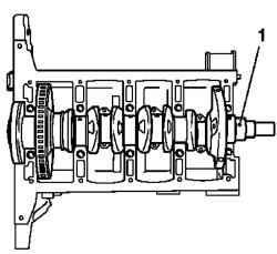
Fig. 2.193. Removing the
crankshaft: 1 - kolechaty shaft
Remove the crankshaft (Fig. 2.193). Disconnect the base of the cylinder block.
NOTE Separate base evenly mounting shovel.
Loosen the bolt 22. Remove the rear oil seal crankshaft. Remove the crankshaft and put on wooden bars. Remove the clamps crankshaft bearings.
NOTE Follow the correct sequence
Remove the connecting rod bearing inserts and label them, while respecting the proper sequence. Check all items for wear and replace if necessary.
Checking crankshaft
Check the roundness of the crankshaft. Check the free running axis of the crankshaft.
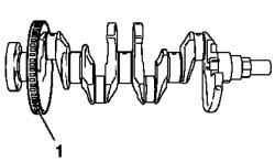
Fig. 2.194. Drive pulse sensor
crankshaft: 1 - CD
Setting
Attach the drive pulse sensor crankshaft and tighten the 3 bolts fastening point 15 Nm Install the crankshaft bearing shells in the cylinder block and the base of the cylinder block. Cover of engine oil.
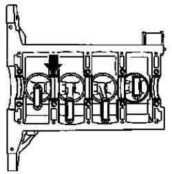
Fig. 2.195. Situation thrust
bearings
Mark the position of thrust bearings (arrow in Figure 2.195). Install connecting rod bearings bushings in connecting rods and connecting rod bearing caps. Cover of engine oil. Carefully set the crankshaft in the cylinder block.
NOTE Position of the crankshaft can be adjusted with a rubber hammer tap on the cheek crank.
Cover the engine oil crankshaft journals. Attach the base of the cylinder block to the cylinder block with new bolts.
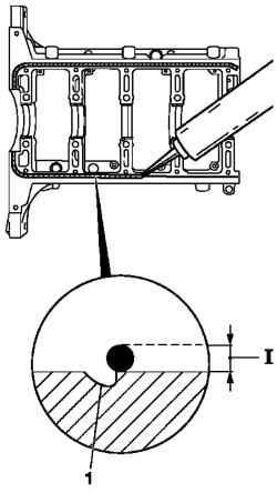
Fig. 2.196. Scheme sealants: 1 -
slot
NOTE Do not apply sealant in the groove. Follow the assembly within 10 minutes.
NOTICE Observe the sequence of delays.
10 Tighten the screws M8 (internal) point 25 N * m, Dauvergne at +60 °. 12 Tighten the screws M6 (external) point of 10 Nm, Dauvergne at +60 °. Remove the remnants of a sealant. Replace rear oil seal crankshaft. Before that apply to the working edge (white) with silicone grease. Install special device KM-235-6 on the neck of the crankshaft.
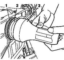
Fig. 2.197. Mounting the rear
flange of the crankshaft: 1 - gasket, 2 - a special device, 3 - a special device for pressing
Put the O-ring on a special device and zapressuyte flush using KM-658-1 (Fig. 2.197).
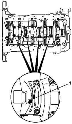
Fig. 2.198. Install covers types of
bearings: 1 - cover
NOTE Pay attention to the loading position, the tides (arrow in Figure 2.198) on the covers of some types of bearings are pointing in the direction of the gearbox.
8 Tighten the mounting bolts moment 13 Nm, Dauvergne at +60 ° +15 °.
NOTE Always use screws M 6,5.
Connect the wiring harness pulse sensor crankshaft. Lock the crankshaft, establishing a special tool KM 952. Smoothly rotate the crankshaft to stop the special tool KM 952. Install new pump seal coolant housing timing mechanism. Ensure correct installation guide bushings (arrows in Figure 2.199)
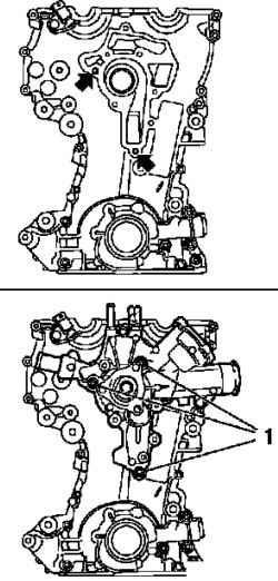
Fig. 2.199. Install the coolant
pump: 1 - bolts fastening
Attach the pump coolant to the body of the mechanism of timing short screws (Fig. 2.199). Tighten the 3 bolts fastening point 8 Nm Apply sealant.
NOTE Housing timing mechanism must be established within 10 min after the application of silicon sealant (gray).
Turn the engine on a special adaptation of the CM 412 at 90 °. Cut off the protruding parts of elastomer gaskets to the cylinder head and replace them with a roller silicon sealant (gray) 2 mm thick.
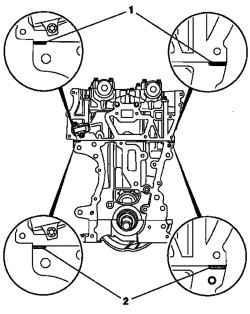
NOTE The roller is a silicone sealant (gray) can be applied directly, if there is no elastomer protrusions (Fig. 2.200).
Installing timing mechanism
Install new gasket body timing mechanism.
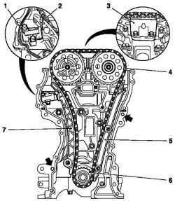
Fig. 2.201. Installing the valve
gear: 1 - timing chain, 2 - a special tool, 3 - slide 4 - timing chain drive mechanism; 5 - slide 6 - Leading gear; 7 - bus clamping
Ensure correct installation guide bushings (arrows in Figure 2.201). Install timing chain drive mechanism.
NOTE When installing, use the new camshaft pulley bolts.
Ensure correct installation guide bushings (arrows in Figure 2.201). Install drive gears. Install asterisk camshaft drive exhaust valves. Tighten the attachment bolt. Install timing chain drive mechanism.
NOTE Provide tension leads (outlet side) branches of the chain drive mechanism for timing.
NOTE Disk-phase sensor must rotate the hand force.
Attach the rail clamp to the cylinder. Tighten the attachment bolt moment 20 Nm Attach the guide to the cylinder block. Tighten the 2 screws fastening point 8 Nm Attach the guide to the cylinder head. Tighten the 2 screws fastening point 8 Nm Loosen the chain tensioner. Remove the special tool KM-955-1. Attach the housing timing mechanism. Tighten the mounting bolts 22. Tighten the screws 6 point 8 Nm Tighten the bolts 14 point 8 Nm Tighten the 2 bolts moment 35 Nm Remove the special tools KM 952 and KM 953
NOTE Special tools should not be used for retention.
Attach the hub of the crankshaft. Check the loading position, the hub of the crankshaft. Label should be facing up.
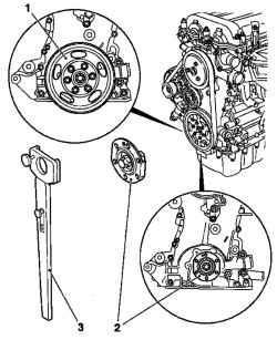
Fig. 2.202. Joining the hub of the
crankshaft: 1 - belt pulley of the crankshaft 2 - the hub of the crankshaft 3 - special tool
Hold with a special tool KM-956-1 / -2 (Fig. 2.202). Tighten the bolt moment 150 Nm, Dauvergne at +45 °.
NOTE Use a new bolt.
Remove the special tool KM-956-1 / -2.
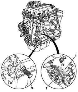
Fig. 2.203. Combining marks on
the belt pulley of the crankshaft with the projection on the case of the mechanism of timing: 1 projection on the case of timing mechanism, 2 - a label on the belt pulley, 3 - special tool
Attach the belt pulley of the crankshaft (Fig. 2.203). Tighten the mounting bolts 6 point 8 Nm Rotate the crankshaft to approximately 720 ° in the direction of rotation of the engine crankshaft bolt hubs. Check belt pulley on the crankshaft is installed in front of the projection on the case of the mechanism of timing (Fig. 2.186). In this position number 1 cylinder cams are located before TDC (both cam facing outwards). Install special tool KM-952. (3) While continuing to rotate the shaft in the direction of rotation of the engine crankshaft hub bolt to lock device KM 952.
NOTE Rotate the crankshaft slowly and smoothly.
In this position, the label on the belt pulley of the crankshaft must be aligned with the projection on the case of the mechanism of timing (see Figure 2.203). Set a special device on the camshaft 953 KM.
NOTE If the device CM 953 can not be established, it is necessary to fulfill the basic ignition timing.
Gadgets KM 953 should be installed in the grooves of shaft until it stops.
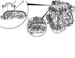
Fig. 2.204. Installation of a special
device KM 954 on the drive sensor phase: 1 - a special device, 2 - Disk sensor phase
Set a special device KM 954 (1) to drive the phase detector (2) and attach to the body of the mechanism of timing (see Figure 2.204).
NOTE If the device CM 953 can not be established, it is necessary to fulfill the basic ignition timing.
Remove appliances KM 954, KM 953 and KM 952. Insert the bolt into the hole base of the cylinder block with a new sealing ring and tighten the torque 60 Nm Remove the remains of seals and sealing surfaces clean. Apply sealant.
NOTE The lid of the cylinder head must be installed within 10 minutes after applying sealant (gray).
Cut off the protruding part of the construction of the shell valve timing mechanism is flush with the cylinder head / body valve timing mechanism.
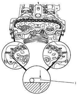
Fig. 2.205. Laying sealer: 1 -
Sealant
Apply the roller (gray) silicone sealant thickness of approximately 2 mm (dimension I) (Fig. 2.205). Replace the cover cylinder head.
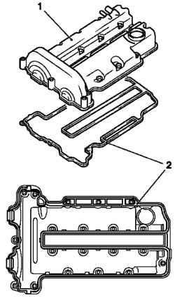
Fig. 2.206. Replacing Cylinder
head: 1 - cover 2 - Seal
NOTICE You need to see the bolts for damage to the seal. If the seal is damaged, the bolt should be replaced.
Attach the lid of the cylinder head to cylinder head Tighten the mounting bolts 13 point 8 Nm Replace ignition module. Connect the ignition module for spark plugs. Tighten the 2 screws fastening point 8 Nm Connect the wiring harness ignition module. Attach the ignition module cover to the lid of the cylinder head. Attach the vent hose to the lid of the engine cylinder head. Attach the pulley to the pump coolant. Tighten the 3 bolts fastening moment 20 Nm Connect the wiring harnesses coolant temperature sensor, camshaft sensor and oil pressure sensor. Secure the wiring harnesses on the cover of the cylinder head. Connect the coolant hoses to the coolant pump and put 2 clamps. Connect the thermostat housing to the upper coolant hose to pump coolant. Install new O-ring. Tighten the 3 bolts fastening point 8 Nm Replace alternator. Install 2 bolts and tighten the moment 35 Nm Attach the wiring harness of the alternator. Connect Poly-V belt tensioner. Tighten the bolt M8 moment 20 Nm Tighten the M10 bolts are 55 Nm
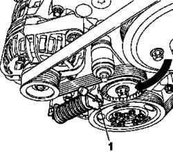
Fig. 2.179 . Ослабление
натяжителя поликлинового ремня: 1 – специальный инструмент
Turn Poly-V belt tensioner in the direction of the arrow (Fig. 2.179), using a device KM 6131, KM6130, install a device. Replace Poly-V belt. Replace Poly-V belt. Pay attention to the direction of rotation and position of the belt. Squeeze the Poly-V belt tensioner device KM 6131. Loosen the tensioner Poly-V belt. Loosen the tensioner Poly-V belt. Attach the support damping engine block to the hull valve gear / cylinder block. Tighten the 3 bolts fastening point 50 Nm Install the flywheel. Install the flywheel. Lock the flywheel using a device KM 652. Clean the threads on the crankshaft. Use new bolts. Use new bolts. Tighten the 6 bolts fastening point 35 Nm, Dauvergne on + 30 °. Attach the clutch. Attach the oil baffle plate to the base of the cylinder. Tighten the mounting bolts 8 point 8 Nm Install oil pan. Install a new oil pan gasket. 16 Tighten the mounting bolts moment 10 Nm Top up the engine oil. Check the engine oil and adjust if necessary.


