2 minute read
Replacing the internal velocity joints


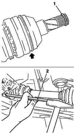
Install wheel shaft in the gearbox, Drive in a gear box with a rubber hammer and a suitable soft metal beard (Fig. 3.106) until it snaps into the locking ring. On vehicles with an intermediate shaft - set the wheel shaft to the intermediate shaft. Replace the retaining ring on the intermediate shaft. Secure the right wheel drive shaft on the intermediate shaft.
NOTICE Be careful not to damage the slots, zapressuyte intermediate shaft using a suitable soft metal beard until it snaps into the locking ring (Fig. 3.106).
Install shaft wheel in the wheel hub. Attach the hinge to the steering knuckle and tighten the moment 50 Nm Use new nut. Attach a swivel arm for supporting the pipe rack and tighten the spring are 55 Nm Use new nut. Hold for Lyskov open wrench. Attach the steering pull to the steering knuckle and tighten the moment of 30 Nm + 90 ° +15 °. Use new nut. Attach the brake hose to the pipe supporting spring rack. Install the brake hose bracket to the supporting tube spring rack. Secure the strap. Install shaft wheel in the wheel hub and tighten the moment of 150 Nm, loosen at 45 °, and then tighten the moment of 250 Nm Use new nut. Hold with Specials tool KM-468-B of the wheel hub. Install the front wheel and tighten the bolts fastening point 110 Nm Check the fluid level in the gearbox.
NOTE Internal Constant-velocity joint is beyond repair, and in case of its failure, should replace the hinge assembly.
Attach the drive shaft in a vise with soft sponges (Fig. 3.107).
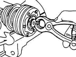
Fig. 3.108. Removing the locking
ring
Using special pliers for removing spring locking ring, remove the circlip from the end of the internal velocity joints (Fig. 3.108).
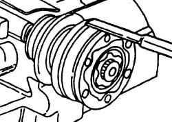
Fig. 3.109. Removing the
protective cover
Using the mandrel, surmount the protective cover from the hinge (Fig. 3.109). Mandrel must in turn be installed in various points around the perimeter of the shell to his uniform withdrawal. Slide the protective cover of mid-shaft.
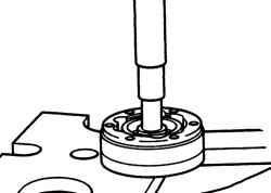
Fig. 3.110. Removing the drive
shaft of the hinge
Mount the hinge in a vise, then remove from the drive shaft. If the drive shaft can not be extract from the joint, the joint is set into a press and using the device, squeeze from the drive shaft (Fig. 3.110). Remove the drive shaft disc springs washer, pre-noting its position. Washer has slots, and the convex side of the washer is on the part of the hinge. Before installing the new hinge thoroughly clean the drive shaft. Install a spring plate washer on the shaft so that the convex side of the puck was at the hinge, and the internal splines compatible with the puck shaft splines.


