7 minute read
Removal, inspection and installation of hard plates and the driven clutch plate (without SAC


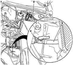
Fig. 3.2. The flow of hydraulic
clutch: 1 - Adapter 2 - a special tool MKM-6174-2, 3 - a special tool MKM6174-1, 4 - valve pumping
Remove the valve cap from the valve pumping and attach a special tool MKM-6174-1 to the valve pumping (Fig. 3.2). Remove air from the clutch. Turn on the device for removing air from the hydraulic drive. Open the valve pumping (2-3 overleaf). Pump to release the brake fluid without bubbles. Close (by hand) valve pumping.
Removing device
Unplug the device for removing air from the hydraulic drive. Disconnect the adapter device for removing air from the hydraulic drive.
NOTICE Must take the following steps to fill the discharge line transmission housing of the working cylinder clutch. When pumping, make sure the tank is filled with hydraulic brake system.
Remove air from the discharge line of the working cylinder clutch. Install special tool MKM-6174-2 at MKM-6174-1 on the valve pumping, lower the free end in a suitable container Press and hold the clutch pedal. Open the valve pumping. Open the valve before pumping air and / or a mixture of air / brake fluid. Close (by hand) valve pumping. Slowly release the clutch pedal and wait approximately 5 seconds. Repeat the procedure four times. Tighten the valve point pumping 5 Nm Remove the special tools MKM-6174-1, and MKM-6174-2. Remove the cap from the valve pumping. Fill the tank hydraulic clutch brake fluid to the mark «MAX». Close the tank hydraulic brake system. Check the opening pressure of the clutch pedal. Check to include all gear with the engine running and clutch depressed.
NOTE Take a test drive to ensure precise work the clutch and braking. The trip was spend with different speeds and frequent gear changes to achieve operating temperatures.
NOTE To prevent damage to the petals spring thrust plate use a special device KM-6263 after removal and installation.
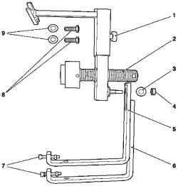
Fig. 3.3. Device for removing and
installing hard plates and driven clutch plate: 1 - pin 2 - retractors, 3 Disc 4 - nut, 5 - KM-6263-4 (short arm), 6 - KM-6263-5 (the long arm ), 7 - lower bolt engine block, 8 upper bolt engine block; 9 - Puck
NOTE Note the different length brackets for joining the CM 6263 at lowering engine block.
Withdrawal
Remove the gearbox
NOTE Special device KM-6263 can be attached only to the engine block, not the oil sump.
Fig. 3.4. Joining device: 1 -
adaptation
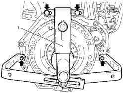
Attach a special device KM-6263 to the engine block and tighten the 4 bolts (arrows in Figure 3.4).
NOTE Do not tighten the bolts.

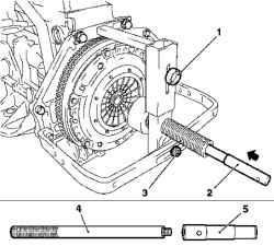
Fig. 3.5. Installing a special device
and alignment mandrel: 1 - pin 2, 4 a special device KM-6263-30, 3 - nut, 4 - aligning arbor
Attach a special device KM-6263-30 (4) to the alignment fixture (Fig. 3.5). Attach a special device KM 6263. Align special device KM-6263 with the center. Set alignment mandrel with a special device KM-6263 KM-30 through 6263 in the drive clutch and the crankshaft (center). Tighten the bolt and nut. Tighten the 4 bolts special device KM-6263 to the engine block (Fig. 3.5). Free slave clutch disc.
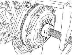
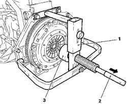
Fig. 3.6. Installation of special
devices: 1 - adaptation
Set a special device KM-6263 so that it was situated opposite the petals spring thrust plate (Fig. 3.6). Turn special device KM-6263 clockwise to the limiter. Remove the thrust plate to the flywheel.
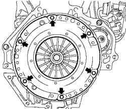
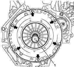
Fig. 3.7. Bolts mounting the
flywheel
6 Loosen the mounting bolts (arrows in Figure 3.7).
NOTE
Figure 3.7 shows the clutch without special adaptations KM 6263 and balancing the mandrel.
Remove the thrust plate and clutch disc. Turn special device KM-6263 counter-clockwise until the limiter and pull the mandrel alignment with a special device KM-6263-30.
Test
Check thrust plate and driven clutch disc wear. Replace if necessary.
NOTE The clutch labor-contaminated products (oil, detergent, etc.) should be replaced. Check the slave clutch disc for damage and wear products on the hub and replace if necessary. Do not empty the thrust plate and driven clutch disc high-pressure cleaners or washing machine.
Check the friction surface of the flywheel on the absence of cracks, burnt and the wear surface. Check the condition of the friction linings and clutch slave drive if they have traces of oil or mechanical damage, replace the slave drive.
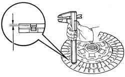
Check the thickness of the lining driven clutch plate, with the help of vernier calipers. Overlays should speak over the heads of rivets not less than 0.3 mm (Fig. 3.8). If the thickness of the lining is less than the permissible or rivet heads are close to the working surface, replace them or slave drive clutch. Check that the springs were not broken and they are no cracks. Check on the lack of wear slots in the hub clutch discs.
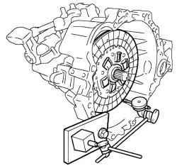
Fig. 3.9. Installing slave drive clutch to the shaft of the gearbox
Replace clutch disc to the shaft of the gearbox (Figure 3.9). Slave clutch disc should be easily and smoothly slide in the slots of the primary shaft of the gearbox.
NOTICE If being replaced clutch slave drive, replace the bearing and clutch.
Using a clock-type indicator, check the pulse of the disc clutch. Minimal beat: 0,8 mm.
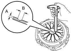
Fig. 3.10. Measuring the depth and
width of wear petals diaphragm spring
Using vernier calipers to check the depth and width of wear petals diaphragm spring (3.10). Maximum: A (Depth): 0,5 mm B (Width): 6,0 mm
NOTE Minor damage to the friction surface can remove the fine-grained sandpaper, but in case of any doubt about the condition of the pressure plate must be replaced.
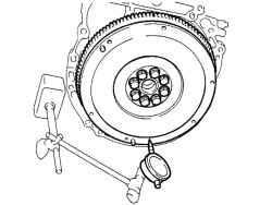
Using a clock-type indicator, check the pulse of the flywheel (Fig. 3.11). Maximum beat: 0,1 mm
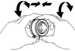
Fig. 3.12. Check bearing clutch
Rotate bearing clutch hand, applying force in the axial direction, check the clutch bearing (Fig. 3.12).
NOTE In bearing lubrication laid, calculated for the entire period of operation, thus, additional lubrication is required. If necessary, replace the bearing clutch.
If you install new parts, be sure to find out what pressure plate and slave drive is required for the designation of the engine and its number, to avoid error. If you set the former in the clutch components, they must first check. Before installing the new pressure plate corrosion protective grease must be removed only at the working surface. In other places, to remove grease in any case is not recommended, because it can significantly reduce the lifetime of adhesion. Make sure the installation of centering pins on the flywheel. Clean the rust on the splines slave drive. Lubricate the teeth of the drive shaft gear box with a thin layer of lubricant MoS2. At stations used for this purpose grease G000100. Then move the slave on the primary drive shaft so that the hub is easily moved about the shaft. Sure to remove excess grease.
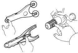
Fig. 3.13. Position of grease on the
clutch fork, fork and pusher and the fulcrum fork
Apply grease on the contact surface couplings and clutch fork, fork and push rod and fulcrum fork (Fig. 3.13). Apply grease to the splines on the clutch and drive shaft splines. Install clutch fork with bearing clutch in the gearbox.
NOTE After installation, move the fork back and forth to check the smoothness of movement Clutch release bearing.
Setting
Attach the slave drive clutch and thrust plate to the flywheel.
NOTE Lettering "Transmission side» should be drawn to the gearbox.
Fig. 3.14. Centering hard plate and clutch plate: 1 - device KM-6263-30
Ottsentriruyte thrust plate and clutch disc alignment mandrel and a special device KM-6263-30 (Fig. 3.14).
NOTE
For clarity, Figure 3.13 shows the clutch without modifications KM 6263.
Tighten the 6 new bolts (arrows in Figure 3.13).
NOTE Do not tighten the bolts.
Attach the thrust plate to the flywheel. Turn special device KM-6263 clockwise to the limiter. 6 Tighten the mounting bolts around 15 N m.
NOTE Tighten the screws crosswise.
Fig. 3.15. Installing slave drive and
the hard plate: 1, 3 - a special device KM-6263-30, 2 - mandrel