8 minute read
Replacing the oil pump (1.4 l


Tighten the 2 screws fastening. 4 Connect the coolant hose. Connect the wiring harness connector coolant temperature sensor. Install pipe cooling system. Tighten the 3 nuts point 9 Nm Attach the 2 coolant hose bracket Install hose air intercooler boost choke on the throttle. Tighten the clamp 2 point 3.5 Nm Replace the cover of the engine. Raise the car completely. Install the bottom cover of the engine compartment. Lower the car completely. Replace the battery pack. Connect the battery pack. Attach the grounding connector to the grounding terminal. Top up the coolant and make sure that it corresponds to the number of normal. Program volatile memory. Close the hood.
2.8. Lubrication
Replacing the oil pump (1.4 l)
Withdrawal
Before the verification procedure warming up the engine to operating temperature (oil temperature 80 ° C). Open the hood. Loosen nuts and disconnect the wire from the massive battery Remove the air filter housing and intake manifold. Disconnect the wiring harness connector sensor mass air flow.
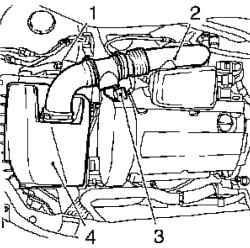
Fig. 2.327. Components, shooting
in the dismantling of the air filter: 1 attachment bolt, 2 - inlet manifold, 3 - the wiring harness connector sensor mass air flow, 4 - air filter housing
Loosen the mounting bolt, remove the collar and the inlet pipe of air filter.
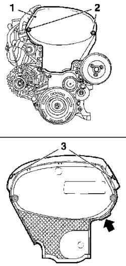
Fig. 2.328. Mounting the front
cover toothed belt: 1 - the front cover of the toothed belt 2 mounting screws, 3 - Latch
Loosen the two mounting screws, disconnect the upper latch and remove the front cover of the toothed belt (top) (Fig. 2.328).
NOTE
Pull the front cover of the toothed belt upwards, the protrusion (arrow in Figure 2.328).
Remove the ignition module in the direction of the arrow shown therein.
NOTE Mark the position of arrows on the lid.
Clear Poly-V belt. Check direction of rotation.
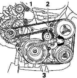
Fig. 2.329. Removing Poly-V belt: 1
- Poly-V belt, 2 - Poly-V belt tensioner, 3 - special tool
Squeeze the Poly-V belt tensioner in the direction of the arrows in Figure 2.329 and lock it with a special tool KM 6130. Remove the guide tube probe for measuring the oil level. Remove the probe. Loosen bolts.
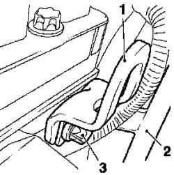
Fig. 2.330. Withdrawal of the guide
tube probe for measuring the oil level and the transport engine brackets: 1 - Transportation clamp Engine 2 - guide tube probe for measuring the oil level 3 - bolts fastening
Remove transport bracket of the engine (Fig. 2.330). Raise the car. Remove the engine splash guard.
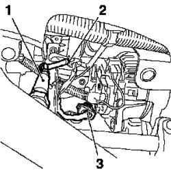
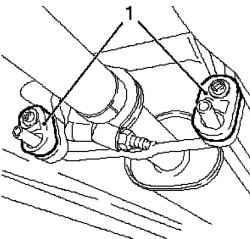
Fig. 2.331. Disconnecting the
supply of oxygen sensor catalytic converter: 1 - oxygen sensor catalytic converter, 2 - wire clamps, 3 - the wiring harness connector
Unplug the wiring harness of oxygen sensor catalytic converter (see Figure 2.331). Remove the wire clamps. Disconnect the wiring harness connector.
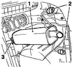
Fig. 2.332. Removing the terminal silencing: 1 - endpoint silencer, 2 rubber bearing 3 - clamp mounting
Remove the endpoint silencer (Fig. 2.332). Loosen the clamp attachment. Loosen nuts and remove the silencer from the bracket. Remove the 2 rubber supports and remove the endpoint from the front muffler muffler. Fig. 2.333. Removing the terminal
silencing: 1 - nuts, 2 - Front Exhaust
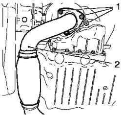
Disconnect the front exhaust pipe (2) from the catalytic converter, 3 unscrewing nuts (Fig. 2.333). Fig. 2.334. Removing the front
exhaust pipe: 1 - rubber bearing
Remove the front exhaust pipe from the front silencer unplugging 2 rubber supports (see Figure 2.334). Place the bottom of the container for collecting liquid. Drain the engine oil. Disconnect the wiring harness connector oil level sensor. Remove the oil pan. Remove the 2 rubber stoppers. Loosen the 3 mounting bolts on the gearbox.
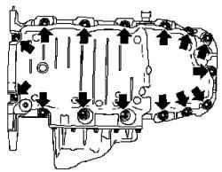
Fig. 2.335. Bolts fixing oil pan
15 Loosen the mounting bolts (arrows) (Fig. 2.335). Remove the oil pan suitable tool. Remove the alternator from the power supply by unscrewing 2 nuts. Remove the 2 bolts.
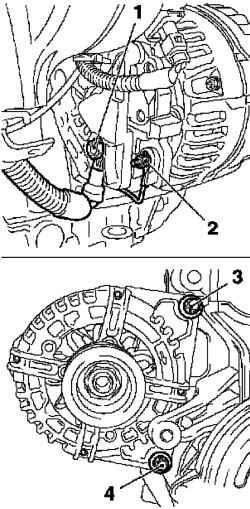
Remove the alternator (see Figure 2.336). Remove the cap.
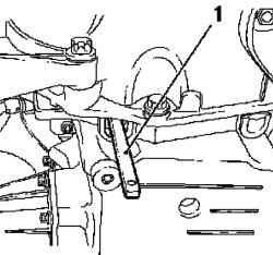
Fig. 2.337. Lock the flywheel: 1 -
special tool
Insert the special tool KM-911 and lock the flywheel (Fig. 2.337). Remove the snubber by unscrewing bolts.
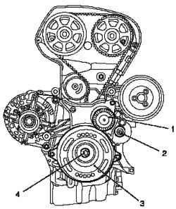
Fig. 2.338. Removing Poly-V belt: 1
- Poly-V belt tensioner, 2 attachment bolt 3 - snubber, 4 - bolt mount
Remove the tensioner Poly-V belt by unscrewing the bolt fastenings (Fig. 2.338). Poly-V belt tensioner is locked with a special tool KM 6130.
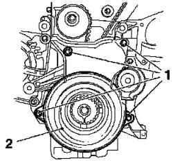
Fig. 2.339. Mounting the front
cover toothed belt: 1 - mounting screws, 2 - the front cover of the toothed belt
Remove the front cover of the toothed belt (bottom) by unscrewing 4 bolts fastening (Fig. 2.339). Install the engine in TDC. Remove the special tool KM 911. Tighten the bolt snubber.
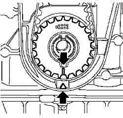
Fig. 2.340. Installing piston
cylinder number 1 in the position of top dead center
Rotate the crankshaft of the engine in the direction of rotation, set the piston cylinder number 1 in the position of top dead center (TDC) (arrow) (Fig. 2.340).
Insert special device KM-6173 (Fig. 2.117).
Attach the KM-6001-A (Fig. 2.118). Fig. 2.118. Installation of a special
device KM-6001-A on the housing front axle: 1 - a special device, 2, 5 neck, 3 - rear support 4 - front support
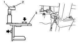
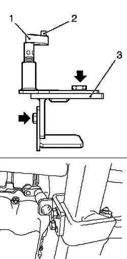
Fig. 2.341. Installation support the
front axle: 1 - prop, 2 - neck, 3 - a special device
NOTE Using the KM-6001-A ensures alignment with the drive housing the front axle.
Fig. 2.342. Installation of a special
device KM-6001-A on the housing front axle: 1 - a special device, 2, 5 neck, 3 - rear support 4 - front support
Loosen the 3 bolts (arrows) in the adjustment tires.
Insert special device KM-6001-A. Necks should be in the holes to the front axle housing. Tighten the 3 bolts fastening the adjustment in the tires. Adjust the support and lift them to the constraints on the neck guides. Tighten the 3 regulatory stud.
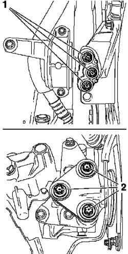
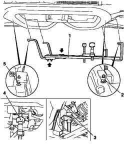
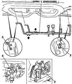
Fig. 2.343. Left and right damping
blocks: 1, 2 - bolts fixing
Adjust the support - front and rear (Fig. 2.343). Raise your legs to the limiter on the neck guide.
NOTE Cervical guide must be placed on piers without a gap.
Lower car Remove damping engine block with the right adapter damping unit by unscrewing 6 mounting bolts (see Fig. 2.343).
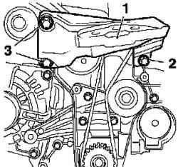
Fig. 2.344. Mounting right support
damping engine block: 1 - right bearing damping block, 2, 3 - bolts fastening
Remove the right support damping engine block, turn away 3 fixing screws (Fig. 2.344). Install camshaft gears, using a special tool KM 6340.
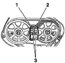
Fig. 2.345. Installing camshaft
star: 1 - a special tool, 2 - a special tool, 3 - tags
Install asterisk camshaft so that the label (3) were located opposite each other (Fig. 2.345). Install special tool KM-6340-left the star camshaft drive the intake valves (I). Install special tool KM-6340 rules. Remove the timing belt, mark direction of rotation.
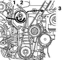
Fig. 2.346. Removing toothed belt:
1 - Allen Key 2 - toothed belt tension roller, 3 - special tool
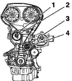
Fig. 2.347. Removing the tensioner
and guide rollers toothed belt: 1 tension roller, 2, 4 - mounting screws, 3 - guide roller
Remove the tensioner and guide rollers toothed belt (Fig. 2.347).
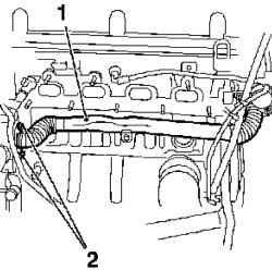
Fig. 2.348. Removing the pipe
cooling system: 1 - pipe cooling system, 2 - bolts fastening
Remove the piping of the cooling system by unscrewing 2 screws fastening (Fig. 2.348). Remove the pump module by unscrewing 8 mounting bolts.
NOTE Bolts are different lengths.
Remove the crankshaft oil seal (front) a suitable tool.
Test
Check the distance between the outer rotor and the pump module.
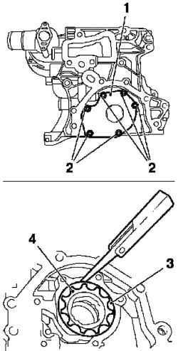
Fig. 2.349. Checking the oil pump:
1 - cover oil pump, 2 - mounting screws, 3 - external rotor, 4 - inner rotor
Remove the oil pump (Fig. 2.349). Check the distance between the outer rotor and oil pump housing. Remove the outer rotor with inner rotor. Visually check nodes.
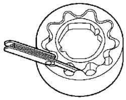
Fig. 2.350. Measuring the gap between the inner and outer rotor
Measure the clearance between the inner and outer rotor (Fig. 2.350).
Setting
Replace the cover oil pump. Tighten the mounting bolts 6 point 8 Nm Replace the pump module.
NOTE The screws are different lengths.
8 Tighten the mounting bolts moment 20 Nm Insert the front O-ring of the crankshaft.
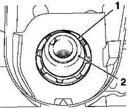
Fig. 2.351. Install the seal ring of
the crankshaft and a protective sleeve: 1 - O-ring of the crankshaft 2 - protective sleeve
Install a protective sleeve on the neck of the crankshaft (Fig. 2.351). Put O-ring shifting it to a protective sleeve on the neck of the crankshaft. Push the O-ring in the crankshaft.
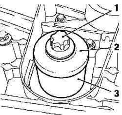
Fig. 2.352. Heat sealing ring: 1 -
pin 2 - Disc 3 - a special tool
Remove the protective sleeve and zapressuyte O-ring in the sump pump with a special tool KM 6351 (Fig. 2.352). Use a bolt and washer drive gears of the crankshaft. Install the remaining components is in reverse order of removal.


