3 minute read
Adjusting the front suspension


Each bus can be identified by code. Narimer: 195 / 70 R 13 108 L
NOTE An explanation of the identification value, see the summary table 4.6.
Dates
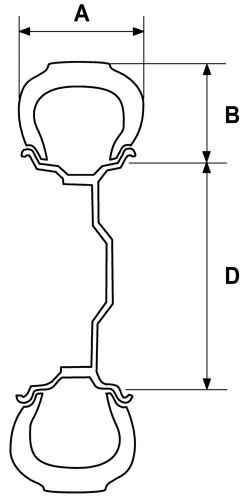
Rim width: The distance between the bead board. Profile height: half the difference between the outer diameter and the nominal rim diameter. Nominal width: width set for the size of an inflated tire, which is installed on the geometrically correct rim. Width: the distance between the outer sides of side walls of an inflated tire, excluding the area with distinguishing mark, decorative edges and wear strips. Overall width: the distance between the outside of the side walls beefiest tire, including higher field due to distinguishing mark, decorative edges and strips of abrasion. Outer diameter: the diameter of an inflated tire in the most remote point of a race surface. Nominal attitude profile: multiplied by one hundred ratio of the height to width of a tire on its rim, presumably established. Payload Bus: The maximum load capacity of a tire which is valid for the specified conditions of use. Tire pressure: The tire pressure refers to the tire pressure at ambient temperature, and does not include an increase in air pressure caused by the tires. Speed index: the index indicates the speed limit the speed at which the tire has a load capacity corresponding to the code of duty for specified conditions.
4.3. Front suspension
Adjusting the front suspension
Preparing Vehicle
Before adjusting the chassis, must satisfy the following conditions: - Should use regular wheels and tires;
- Check the profile tires - wear and tear should be uniform; - Make sure the tire pressure corresponds to full load. The pressure in the left and right tires of each axle must be the same; - All the wheels and wheel bearings must be in excellent condition; - Chassis must be undamaged, and the gaps in the ball joints (steering) or nodes of suspension are not allowed. Check the collapse of the wheels, the angle of the longitudinal axis of rotation of the wheels and toe. The following operations must be performed before the adjustment of the chassis: - Fuel tank is refueled by half; - The car must be unloaded; - Set the car in position for adjustment. In all operations the car must be on a horizontal surface; - Check and adjust the equipment to adjust the chassis of a car in accordance with the manufacturer's instructions; - Set the steering wheel in position rectilinear motion.
Camber
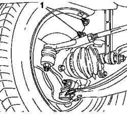
Fig. 4.24. Bolts supporting pipes
spring stands at a turning fist: 1 Bolts
Raise the front of the car. The corresponding front wheel must be posted. Unscrew the two bolts supporting the pipe spring stands at a turning fist. Install new bolts and nuts - set threaded screw connection freely (Fig. 4.24).
NOTE The operations described below may be used only to adjust the collapse of the wheels in a limited range.
Pull the front wheel on top and set the maximum positive disintegration. Tighten the two bolts supporting the pipe spring stands at a turning point fist 10 N * m to hold down a spring rack in the steering knuckle. Slowly lower the car on wheels. The collapse of the change in "negative" side - if necessary, turn the front wheel with his hands. When the "nominal value" collapse, tighten the bolt, a spring connecting the rack with swivel - torque 80 Nm +60 ° +15 °.
Test / inspection
Swing the car several times and then check the camber of the wheels. Adjusting the convergence of the front wheels.


