2 minute read
Removing and installing front brake hoses


Attach the wiring harness. Connect the wiring harness connector to the sensor pedal. Attach a bracket. Connect the wiring harness connector switch signal inhibition. Attach the intermediate shaft to the steering shaft, tighten the moment 24 Nm Slide the intermediate shaft on the steering shaft. Attach the clamping bolt.
NOTE Before installing the clamping bolt, make sure that the groove (arrow in Figure 6.17) the steering shaft is combined with a hole in the intermediate shaft.
Clean the threads and install the bolt with a fixing composition. Pay attention to the loading position, the clamping bolt. Attach the intermediate shaft to steering gear and tighten the moment 24 Nm Insert the intermediate shaft in the steering mechanism.
NOTE Make sure that the wheels are in the position of the rectilinear motion.
Attach the clamping bolt.
NOTE Before installing the clamping bolt, make sure that the groove (arrow) of the steering shaft is combined with a hole in the intermediate shaft.
Clean the threads and install the bolts with a fixing composition. Check the position of the rectilinear movement, adjust if necessary. Install ducting from the driver. Insert rivet. Set facing the driver's side. Install 2 time. Install the lower instrument panel pad. Install central light switch. Connect the wiring harness connector. Install central light switch. Install central light switch in the leftmost position. Install casing pipe supports the steering column below. Replace the cover ignition. Install casing pipe supports the steering column top.
Withdrawal
Fill the tank hydraulic brake system to the mark «MAX» and close with a special tool MKM-558-10. Remove the front wheel. Loosen the screw type "Banjo" (3) of the brake caliper.
NOTE Assemble the brake fluid flowing, and close the hole.
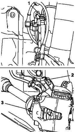
Fig. 6.20. Disconnect the brake
hose: 1 - tube of the braking system, 2 - strap, 3 - screw type "banjo"
Remove the strap and choke tubes braking system (1) of the brake hose (Fig. 6.20). Remove the brake hose with attachment.
Setting
Attach the brake hose to caliper bolt type "banjo" with the new O-rings and tighten the moment 40 Nm Attach the brake pipe to the brake hose and tighten the moment 14 Nm
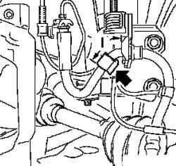
Fig. 6.21. Mounting size tread
NOTE Install the brake hose to the chassis IDS +. Write down the size of the assembly (I) of the tread (arrow in Figure 6.21).
Mounting dimensions (I): 53 mm.


