2 minute read
Replacing the brake pedal


NOTE To adjust the status of the parking brake in the brake caliper or brake drum - make sure that every time when you turn on the parking brake, the brake pedal is returned to its original position (fully unloaded). In cars with drum brake adjuster lever mechanisms of the work can not hear.
Lift the lever of the parking brake system 5 times until it stops and then pull down. Lift the lever of the parking brake for 2 clicks. Turn the adjusting nut on the parking brake lever system before any appreciable resistance to rotation of the rear wheels.
NOTE Inhibitory force must be equal on both wheels.
Lift the lever of the parking brake system on the 3 steps.
NOTE The wheels should be blocked by 3 clicks.
Attach the corrugated cuttings of the parking brake lever on the center console. Attach the lid of the diagnostic compounds.
Withdrawal
Remove the casing pipe supporting the steering column from the top by unscrewing 2 screws fastening. Remove the casing pipe supporting the steering column from the bottom, unscrewing 3 bolts.
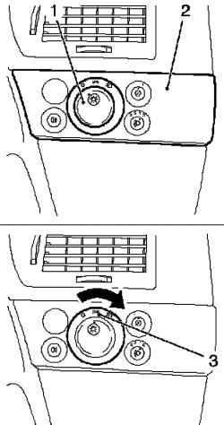
Fig. 6.15. Removing the module
light switch: 1 - Grip 2 - central location, 3 - light switch module
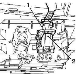
Fig. 6.16. Removing the wiring
harness connector module light switch: 1 - secondary fuse, 2 - fuse
Separate wiring harness connector module light switch. To do this, push the secondary fuse and unlock the fuse (Figure 6.16). Remove the lining of the bottom lining of the instrument panel by unscrewing the 4 screws fastening. Remove the lining of the driver, removing the 2 time. Remove the duct from the driver. Remove the rivet. Lock the steering wheel in the position of the rectilinear motion. Turn the steering wheel in position rectilinear motion. Remove the key from the ignition. Block locking steering column.
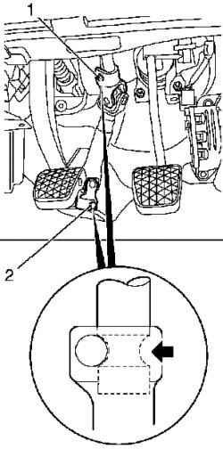
Fig. 6.17. Clamping bolts, steering
column: 1, 2 - clamping bolts
NOTE Check the loading position, clamping bolts.
Remove the intermediate shaft. Disconnect the wiring harness. Disconnect the wiring harness connector switch signal inhibition. Unleash the bracket. Disconnect the wiring harness connector, the sensor pedal. Remove piston brake booster from the brake pedal. Loosen the screw fastening the brake pedal. Remove the fixing spring. Remove the bolt on brake pedal. Remove the damping unit. Remove the brake pedal with the support of the bearing by unscrewing 2 screws and 4 nuts.
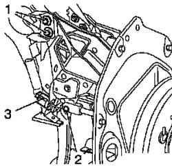
Fig. 6.18. Removing the brake
pedal: 1 - bolts, 2 - attachment bolt the brake pedal, 3 - switch braking signal
Disconnect the brake switch signal from the holder (Figure 6.18).
Setting
Install signal inhibition. Install the brake pedal with the support bearing tighten the mounting moment 20 Nm Set damping unit. Attach piston brake booster to the brake pedal.
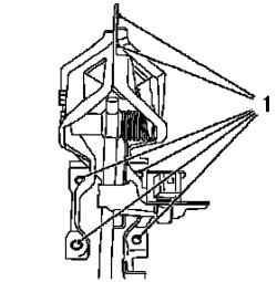
Fig. 6.19. Bolt fastening the brake
pedal: 1 - bolts, 2 - screw fixing
Install bolt brake pedal.


