2 minute read
Replacing the piston rod with


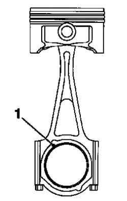
The rush to the cranks should be turned in the direction of transmission (Fig. 2.238).
NOTE If one of these two elements must be replaced, replace all the nodes in the block (piston, piston rings, piston pin and connecting rod) new.
Fig. 2.239. Build a special tool
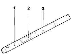
Assemble guide bolt using special instruments KM-634-6 (1), KM-634-7 (2) and KM-634-5 (3) (Fig. 2.239).
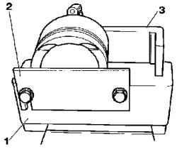
Fig. 2.240. Special tools for
assembling the piston
NOTE Hole piston pin must be placed horizontally.
Set KM-634-4 (3) of KM-634-1 (Fig. 2.240). Tighten the bolts by hand. Securely fasten the piston, using the KM-634-2 (2) that he could not shift (Fig. 2.240). Determine the depth of the pressing piston pin. Zapressuyte node (1), consisting of the KM-634-6, KM-634-7, and KM-634-5 hole in the piston pin and connecting rod to achieve the KM-634-7 central position in the piston.
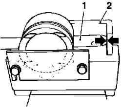
Fig. 2.241. Mounting node in the
piston
In this position, KM-634-4 (2) should be against the edge node (arrows) (Fig. 2.241). Tighten bolts KM-634-4. Remove the KM-634-7 with the guide bolt and replace the new (oiled) piston pins. Heat a new crank in the upper part of the heating plate. Put the upper end of connecting rod on a heating plate.
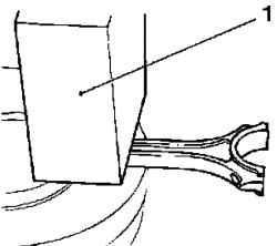
Fig. 2.242. Removing the heat loss
through the refractory brick: 1 firebrick
Reduce heat loss through the refractory bricks (Fig. 2.242). Temperature settings: from 280 ° C to 320 ° C
NOTICE Re-machining the connecting rod is impossible, because he has no balancing pins. Observe the correct location device.
The rush to the rods should be opposite the arrows on the bottom of the piston (Fig. 2.243).
Install piston on the piston rod with.
NOTE Stuck piston can not be pressed - to perform the installation quickly.
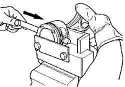
Fig. 2.244. Installing piston pin
Zapressuyte unit, consisting of KM-634-6, piston pin and KM-634-5 smoothly and without delay through the hole piston pin and crank all the way into KM-634-4 (Fig. 2.244). Fig. 2.245. The components of the
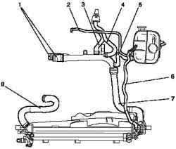
cooling system (engines 1,4-1,6 l): 1 - the coolant expansion tank, 2 connecting a hose from the expansion tank to the radiator, 3 heater, 4 - elbow pipe of the lower radiator hose, 5 - a coupling to refrigerator exhaust gas recirculation, 6 - tube cooling exhaust gas recirculation; 7 thermostat, 8 - relapsing hose, radiator heater, 9 - delivery hose, radiator heater, 10 - connecting a hose from the choke to the expansion tank, 11 - connecting a hose from the cooling circuit of the engine to the expansion tank