Electrical/Control Systems Lift Arm and Standard Auxiliary Flow Control Module (Maestro Controller 1)
Optional High-Flow Module (Early Machines)
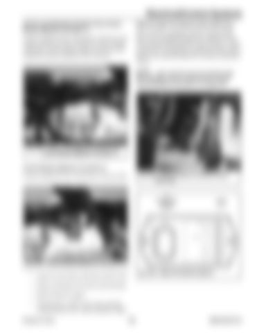
Early machines equipped with the optional highflow have an additional high-flow module (S, Fig. 544) installed underneath the multi-function control module (N). The high-flow module provides control logic for the optional high-flow auxiliary hydraulics circuit.
Control module (P, Fig. 538 and Fig. 542) acts as an output extension for the main/drive control module (controller 2) and includes outputs for lift arm and standard auxiliary hydraulics flow function.
NOTE: Later machines have the optional highflow integrated into the “Multi-function Control/ Interlock Module (Controller 3)” on page 301.
N Q
Fig. 542 – Lift Arm and Standard Auxiliary Flow Control Module (Maestro Controller 1) S
Control Module (Maestro Controller 2) Fig. 544 – Optional High-Flow Module (Early Machines)
Control module (R, Fig. 538 and Fig. 543) provides:
J1 Connector (Pins)
LEDs
R
Fig. 543 – Control Module (Maestro Controller 2) Fig. 545 – High-Flow Module (Option)
• Logic for travel drive and main control valve • Pump swash plate I/O sensors and solenoids • Bucket function outputs • Transmission, control valve and controller communication error codes broadcast output Printed in U.S.A.
303
50940165/C0718


