
1 minute read
Lift Arm and ROPS/FOPS


Lift Arm Removal
NOTE: Some machines may vary slightly from what is shown in the photographs in this manual. Procedures are similar, however, in all cases.
NOTE: Label all hoses and note their locations before disconnecting to ensure correct installation.
IMPORTANT: Park the machine where the lift arm can be supported with a overhead hoist or similar device.
NOTE: Some loss of hydraulic oil will occur when disconnecting hydraulic hoses. Use absorbent mats to catch any dripping oil when disconnecting hoses. Cap and plug hydraulic lines after disconnecting.
IMPORTANT: Always dispose of hydraulic fluids according to environmental laws or take to a recycling center for proper disposal. DO NOT pour onto the ground or down a drain.
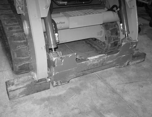
1.Complete the Mandatory Safety Shutdown Procedure, with the exception of lowering the lift arm onto blocks (A, Fig. 177) to support the front of the lift arm. See “Mandatory Safety Shutdown Procedure” on page22.
4.Raise the ROPS/FOPS according to “Raising ROPS/FOPS” on page140.
Warning
Always secure the ROPS/FOPS in the tilted position with pins and spring pins. Never allow anyone under the ROPS/FOPS if the tilt securing pins are not in place.
5.Perform steps 5-a through 5-d for both lift cylinders.
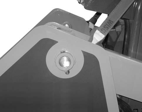
a.Remove locknut (B, Fig. 178) and screw (C) from lift cylinder pivot pin (D).
2.Operate controls with the engine off, power on, to relieve hydraulic pressure.
3.Disconnect the negative cable from the battery.
b.Support lift cylinder (E).
c.Drive pivot pin (D) out of lift cylinder (E) and lift arm.
d.Lower lift cylinder (E), and support it using a block.
6.Lower the ROPS/FOPS according to “Lower ROPS/FOPS” on page142.
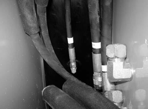
7.Disconnect, cap, and plug left-side (standard) auxiliary hydraulic hoses (F and G, Fig. 179) and fittings.
8.Disconnect, cap, and plug left-side (standard) auxiliary return line (H) and fittings.
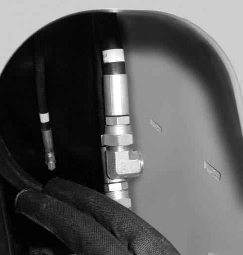
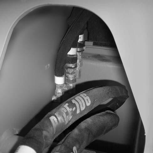
9.On machines equipped with the high-flow auxiliary hydraulics option: a.Disconnect, cap, and plug right-side (highflow) auxiliary hydraulic hoses (Iand J, Fig. 180) and fittings. b.Disconnect, cap, and plug high-flow auxiliary hydraulic return hose (K, Fig. 181) and fittings.
10.Disconnect, cap, and plug bucket cylinder hydraulic hoses (L and M, Fig. 182) from the tubes on the right side of the lift arm.
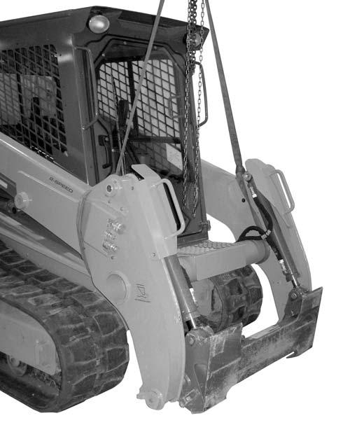
11.Support lift arm (N, Fig. 183) using an overhead hoist or other appropriate lifting device.
12.On both sides of the lift arm: a.Remove locknut (O) and screw (P) from lift arm (N) and pivot pin (Q). b.Drive pivot pin (Q) from lift arm (N).

13.Remove lift arm (R, Fig. 184), by moving it forward slightly, and then lifting it free of the machine.
Lift Arm Installation
1.On both sides of the lift arm: a.Using an overhead hoist or other appropriate lifting device, move lift arm (A, Fig 185) into place, and install pivot pin (B).
Warning
Keep hands and feet clear when positioning lift arm on the machine. Severe pinching/crushing injury can occur.


