1 minute read
Model 2500RT Engine Removal/Installation


NOTE: 1/2” capscrews (S) should be replaced for installation. Refer to the parts manual for ordering information.
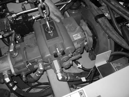
49.Attach a lift bracket (X, Fig. 255) to the top of the hydraulic pump, to allow lifting the hydraulic pump using a hoist (Y).
NOTE: Lift bracket (X) needs to be fabricated. Threading for mounting bracket holes for lift bracket (X) is M12-1.75.
50.Lift the hydraulic pump slightly, and pull the pump forward until it clears the engine.
NOTE: A come-along hand winch may be required to pull the hydraulic pump forward.
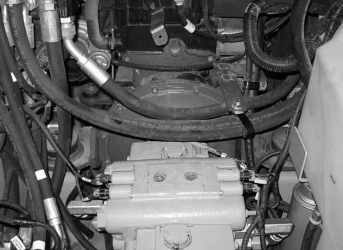
51.Remove two rear motor mount screws (E, Fig. 256) and large washers (F). Discard screws (E), but retain washers for installation.
NOTE: Screws (E) should be replaced for installation. Refer to the parts manual for ordering information.
52.Lower the ROPS/FOPS according to “Lower ROPS/FOPS” on page142.
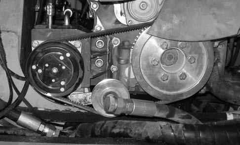
53.For machines equipped with air conditioning: a.Remove the air conditioning compressor belt. b.Remove two air conditioner compressor mounting screws (G, Fig. 257). Position the air conditioner compressor assembly to provide clearance for engine removal.


