1 minute read
Models 1750RT/2100RT Tier 4 Engine Removal/Installation


20.Lift the hydraulic pump slightly, and pull the pump forward until it clears the engine.
NOTE: A come-along hand winch may be required to pull the hydraulic pump forward.
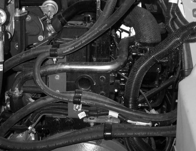
21.Remove screws (L, Fig. 319) securing hose/ cable clamp bracket (O) to the engine block. Retain screws (L) for installation.
22.Remove 3 screws securing hose/cable clamp bracket (M) to the engine block. Retain screws for installation.
23.Remove screw (N) securing the battery ground cable to the engine block. Retain screw (N) for installation.
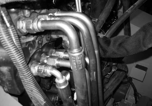
IMPORTANT: Label tubes (O, Fig. 320) and note their locations to ensure correct installation.
24.Disconnect tubes (O) from the control valve.
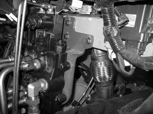
25.Remove screws (F, Fig. 321) securing the control valve mounting bracket. Carefully move control valve (G) to allow access to right front engine mounting bracket. Retain screws (F) for installation.


