1 minute read
Models 1750RT/2100RT Tier 4 Engine Removal/Installation


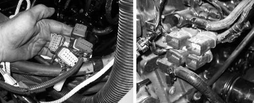
29.Make electrical connections (J, Fig. 374) at the left front of the engine.
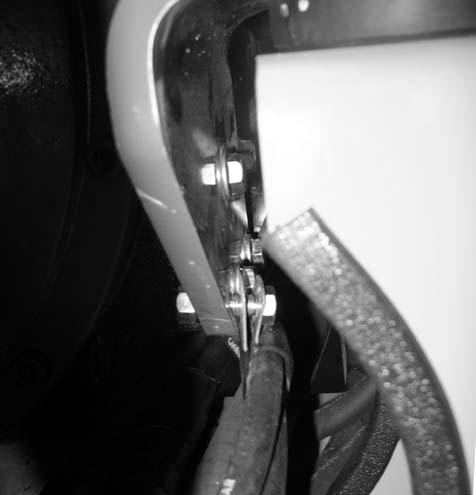
31.Install new screws (H, Fig. 376) and large flat washers (I) in both front motor mounts. Torque screws (P) to 813 Nm (600 lb.-ft.).
NOTE: Use new screws (H) for installation. Refer to the parts manual for ordering information.
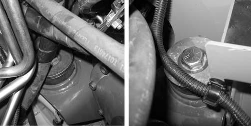
30.Secure fuel line (L, Fig. 375) to the left front engine mount using clamp (K). Tighten securely.
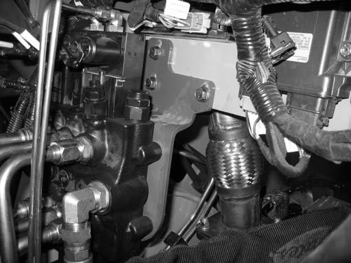
32.Position control valve / mounting bracket (G, Fig. 377) against the front side of the firewall. Secure the control valve / mounting bracket using screws (F).