
1 minute read
Model 2500RT Engine Removal/Installation


37.Loosen clamp (U, Fig. 247) securing the air cleaner to the intake tube (V).
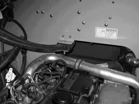
41.Disconnect hose retainer (X, Fig. 249), and pull heater supply and return hoses (Y) from the engine compartment.

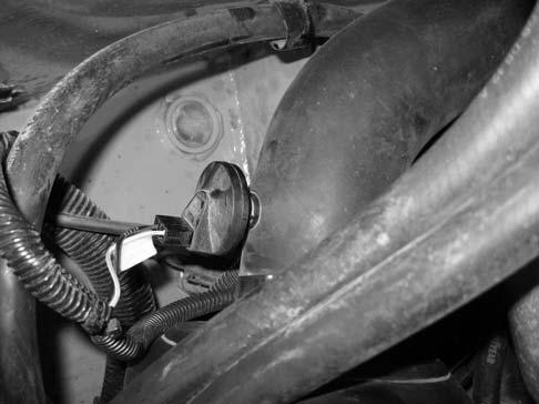
38.Disconnect wiring connector (W, Fig. 248) from the air cleaner pressure sensor.
42.Loosen the clamp (Z, securing the air intake tube to the turbocharger (A).
39.Raise the ROPS/FOPS according to “Raising ROPS/FOPS” on page140.
Warning
Secure the ROPS/FOPS in the tilted position. Do not allow anyone under the ROPS/FOPS if the tilt securing mechanism is not in place.
40.Remove hydraulic pump assembly. See “Hydrostatic Pump Removal” on page270.


