1 minute read
Tier 4 Engine Removal/Installation


75.Remove nut (E, Fig. 438) and screw (F) from left rear motor mount (G), and remove hose bracket (H).
76.Remove screws (I) and washers (J) from both rear motor mounts. Discard screws (I), but retain washers for installation.
NOTE: Screws (I) should be replaced for installation. Refer to the parts manual for ordering information.
NOTE: Use caution when removing engine, as some hoses may need to be moved aside.
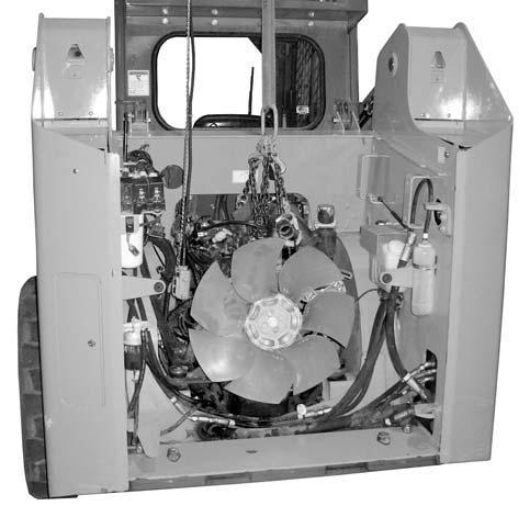
77.Remove engine (K, Fig. 439) using an engine hoist or other appropriate lifting device.
Interim Tier 4 Engine Installation
Model 1750RT (S/N 131000 and Before)
Model 2100RT (S/N 241000 and Before)
IMPORTANT: Always verify electrical connections are sound and strain-relieved when static and to accommodate moving components and machine operation. Route, tie and clamp all wires and connections to avoid pinching, chafing and damage consistent with factory design and practice.
1.Carefully lift engine (A, Fig. 440) into place using an engine hoist or other appropriate lifting device.
Warning
Keep hands and feet clear when positioning the engine in the machine. Severe pinching/ crushing injury can occur.
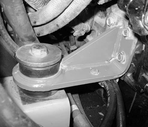
2.Install new screws (B, Fig. 441) and washers (C) in both rear motor mounts (D). Torque screws (B) to 298 Nm (220 lb.-ft.)
NOTE: Use new screws (B) for installation. Refer to the parts manual for ordering information.
3.Install hose clamp (E) with fuel line on left motor mount (D) using screw (F) and nut (G). Tighten securely.
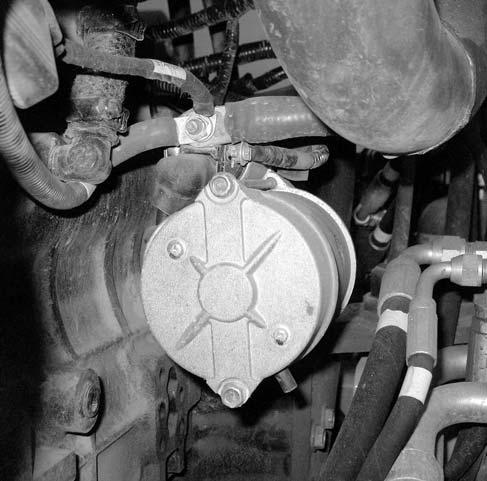
4.Connect cable (H, Fig. 442) to starter motor (S) using nut (I). Tighten securely.
5.Connect wire (J) to starter motor (S) using screw (K) and washer (L). Tighten securely.
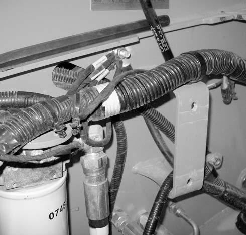
6.Connect the fuel pump wiring connector (M, Fig. 443) to the wiring harness.
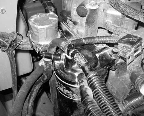
8.Connect fuel return line (P) to the fuel filter using hose clamp (O). Tighten securely.
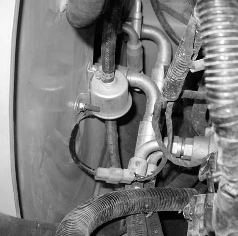
9.Connect ground cable (Q, Fig. 445) to the frame using nut (R). Tighten securely. Secure ground cable (Q) to the wiring harness using cable ties (S) as needed.
7.Connect fuel hose (N, Fig. 444) to the fuel filter using hose clamp (O). Tighten securely.
10.Connect engine wiring harness main connector (T, Fig. 446) to main harness (U).
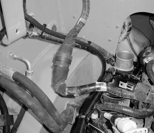
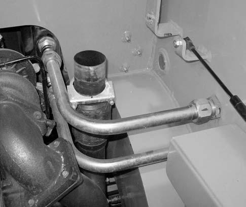
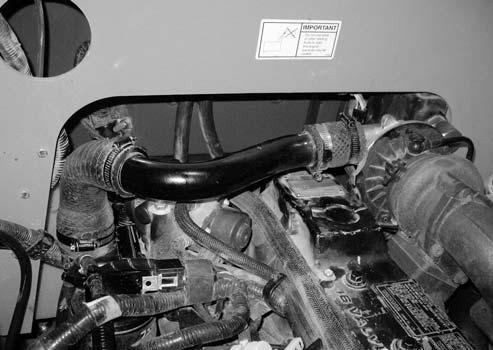
11.If it was removed, install turbocharger crossover tube (V, Fig. 447.) to the turbocharger outlet and engine intake. Secure using 2 clamps (W).
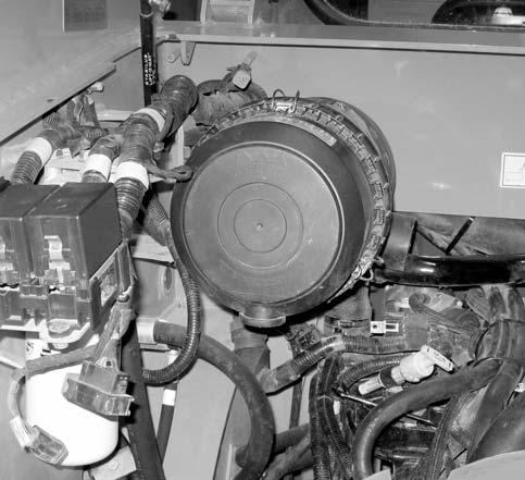
12.Install air cleaner assembly (X, Fig. 448), using 2 carriage bolts (Y), flat washers (Z), and locknuts (A). Tighten securely.