1 minute read
Lift Arm and ROPS/FOPS


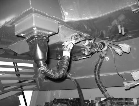
16.Remove 6 cable ties (G, Fig. 198).
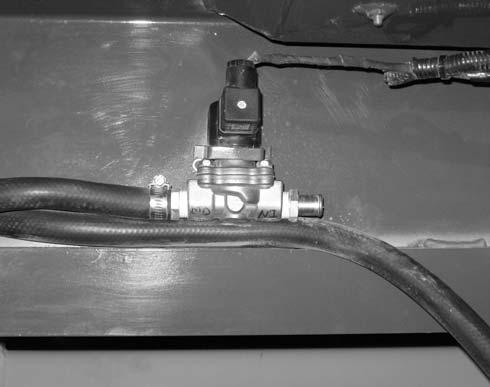
17.Loosen hose clamp (K), and disconnect heater hose (L) from heater control valve (M).
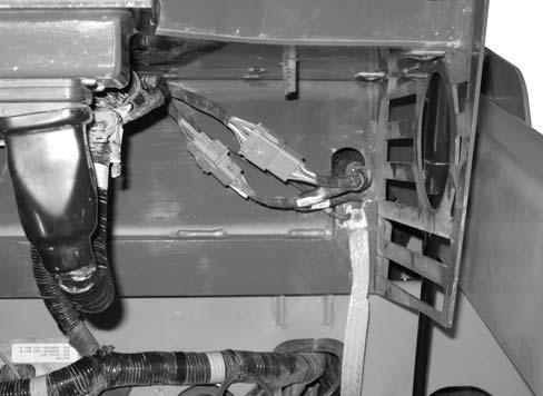
21.Disconnect wiring connectors (P and Q, Fig. 200).
NOTE: Label all wires and wiring connectors before disconnecting to ensure correct installation.
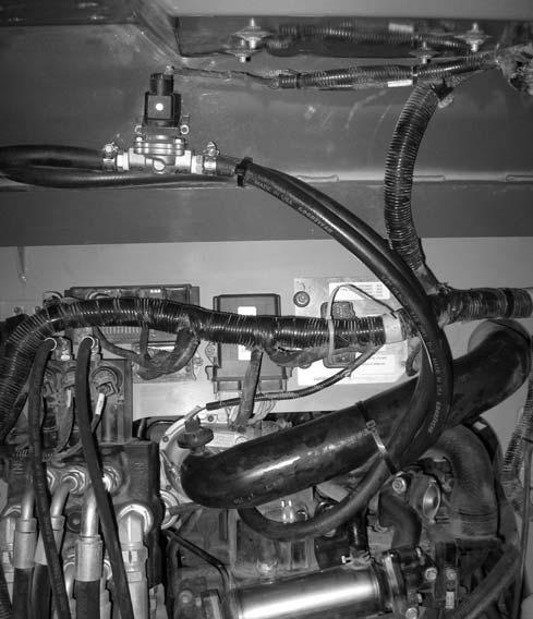
18.Remove cable ties (G).
19.Pull heater return hose (N) from engine compartment.
20.Disconnect wiring connector (O, Fig. 199) from the heater control valve (M) solenoid.
NOTE: Label all wiring connectors before disconnecting to ensure correct installation.
22.Remove nut (R), and remove ground strap (S) and ground wire (T).
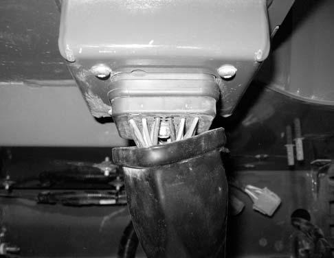
23.Pull boot (U, Fig. 201) down and remove retaining screw (V). Disconnect connector (W).
Lift Arm and ROPS/FOPS
25.On both sides of the ROPS/FOPS, hold support struts (Y, Fig. 202), and remove spring clip (Z) and pin (A). Lower the support struts.
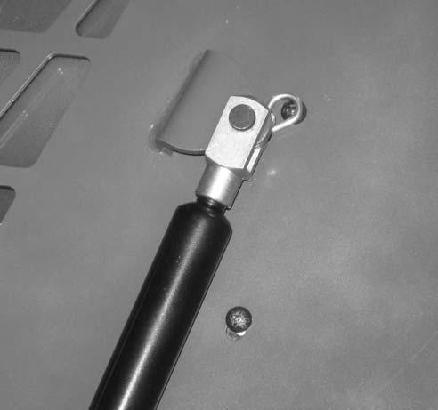
24.Remove cable clamps (X) from the back of the ROPS/FOPS.
IMPORTANT: An assistant is required for the remainder of the ROPS/FOPS removal procedure.
26. Lower the ROPS/FOPS.
27.Rig the ROPS/FOPS for removal using an appropriate lifting device, and support the ROPS/FOPS in the raised position with the lifting device.
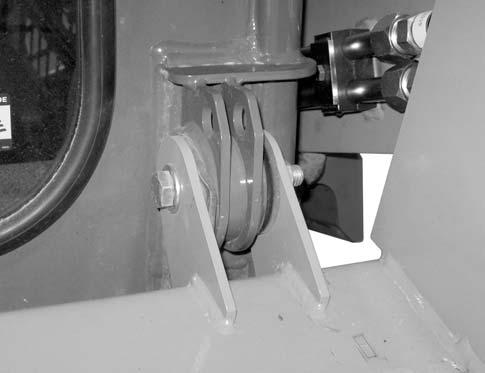
28.On both sides of the ROPS/FOPS, remove nut (B, Fig. 203), screw (C), and 2 flat washers (D).