1 minute read
Model 2500RT Engine Removal/Installation


24.Install turbocharger intake tube (L, Fig. 289). Secure the intake tube to the turbocharger and air cleaner using clamps (M).
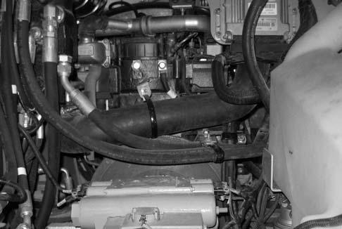
26.Feed supply and return heater hoses (O, Fig. 291) into the engine compartment. Install heater hose retainer (P).
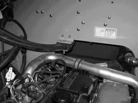
25.Only early machines, install intake tube mounting bracket screw (N, Fig. 290).
NOTE: Later machines have a diffrent intake hose without bracket and clamp shown in Fig. 290.
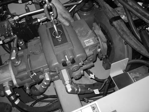
27.Attach a lift bracket (X, Fig. 292) to the top of the hydraulic pump, to allow lifting the hydraulic pump using a hoist (Y).
NOTE: Lift bracket (X) needs to be fabricated. Threading for mounting bracket holes for lift bracket (X) is M12-1.75.
28.Lift the hydraulic pump slightly, and pull the pump rearward, meshing the splined driveshaft on the pump into the engine. Pull the pump tight against the engine.
NOTE: A come-along hand winch may be required to pull the hydraulic pump rearward against the engine.


