1 minute read
Lift Arm and ROPS/FOPS


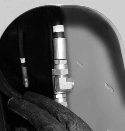
b.Connect right-side (high-flow) auxiliary hydraulic hoses (H and I, Fig. 188).
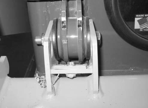
6.For both lift cylinders: a.Raise lift cylinder (M, Fig. 190), align the rod end of the cylinder with the pivot pin opening, and install pivot pin (N).
4.Connect b.Install screw (O) and locknut (P).
7.Check the hydraulic system oil level according to “Checking Hydraulic Oil Level” on page131. Add oil if necessary. Refer to “Fluids/Lubricants Types and Capacities” on page37 for proper hydraulic oil specifications.
8.Reconnect the negative cable to the battery.
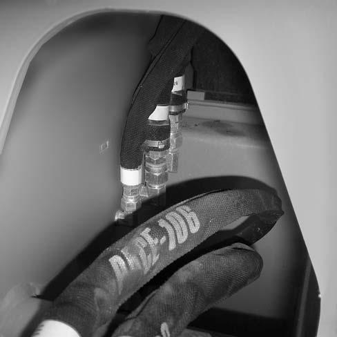
5.Connect left side auxiliary return line (L)

ROPS/FOPS Service
Refer to the Parts Manual for specific service parts information when servicing the ROPS/FOPS, especially door components.
ROPS/FOPS Removal
IMPORTANT: Park the machine where the ROPS/FOPS can be supported with a overhead hoist or similar device.
NOTE: Some machines may vary slightly from what is shown in the photographs in this manual. Procedures are similar, however, in all cases.
1.Complete the Mandatory Safety Shutdown Procedure. See “Mandatory Safety Shutdown Procedure” on page22.
2.Disconnect the negative cable from the battery.
3.Access the engine compartment according to “Engine Access” on page119.
4.Drain the cooling system according to “Draining/Refilling Cooling System” on page125.
IMPORTANT: Dispose of waste coolant according to environmental laws. DO NOT pour coolant onto the ground or down a drain.
NOTE: The capacity of the cooling system is approximately 13-19 L (3.5 - 5.1 gals.).
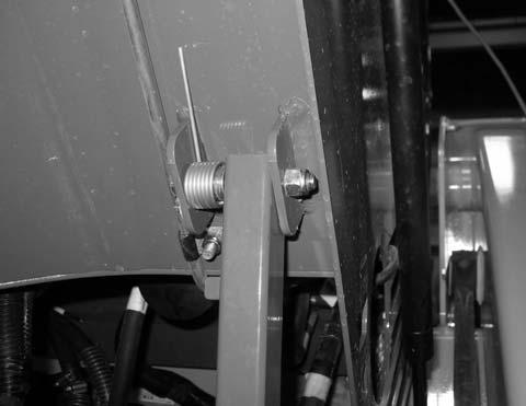
5.Remove nut (X, Fig. 191) securing ROPS/FOPS prop bar (Y). Remove hardware securing prop bar (Y) to the bracket on the bottom of the ROPS/FOPS, noting the position of the hardware components for reassembly.
NOTE: ROPS/FOPS prop bar (Y) needs to be removed to allow ROPS/FOPS support struts (Y, Fig. 202) to extend to completely to the relaxed position.
6.Model 1750RT (Serial Numbers 30870 and before), and Model 2100RT (Serial Numbers 40420 and before) a.Remove bolt (F, Fig. 192) securing ROPS/ FOPS tilt stop plates (H). Remove tilt stop plates (H). Retain tilt stop plates (H) and bolt (F) for reassembly.
Model 1750RT (Serial Numbers 30870 and Before) Model 2100RT (Serial Numbers 40420 and Before)