1 minute read
Models 1750RT/2100RT Tier 4 Engine Removal/Installation


Tier 4 Engine Removal
Model 1750RT (S/N 131001 and Up)
Model 2100RT (S/N 241001 and Up)
IMPORTANT: Park the machine where the engine can be supported and removed with an engine hoist or similar device.
NOTE: Some machines may vary from what is shown in the photographs in this manual. Procedures are similar, however, in all cases.
NOTE: Label all hoses and electrical connections and note their locations before disconnecting to ensure correct installation.
1.Complete the Mandatory Safety Shutdown Procedure. See “Mandatory Safety Shutdown Procedure” on page22.
2.Disconnect the negative cable from the battery. Secure the cable away from the battery terminals.
Warning
Secure the negative cable away from the battery terminals to prevent sparking and unintentional electrical connections.
3.Access the engine compartment according to “Engine Access” on page119.
4.Drain the cooling system according to “Draining/Refilling Cooling System” on page125.
IMPORTANT: Dispose of waste coolant according to environmental laws. DO NOT pour coolant onto the ground or down a drain.
NOTE: The capacity of the cooling system is approximately 15 L (4 gals.).
5.Drain the hydraulic reservoir system according to “Changing Hydraulic Oil and Filter” on page132.
IMPORTANT: Always dispose of hydraulic fluids according to environmental laws or take to a recycling center for proper disposal. DO NOT pour onto the ground or down a drain.
NOTE: The capacity of the hydraulic reservoir is approximately 80 L (21.5 gals.).
6.Raise the ROPS/FOPS according to “Raising ROPS/FOPS” on page140.
Warning
Secure the ROPS/FOPS in the tilted position with the tilt prop bar. Do not allow anyone under the ROPS/FOPS if it is not supported in the raised position.
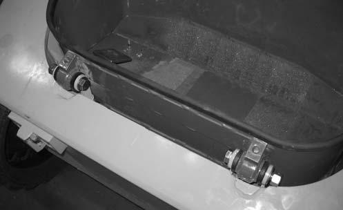
7.Remove hardware (X, Fig. 312) securing foot tub (U). Lift foot tub (U) and disconnect electrical connector from the foot throttle. Remove foot tub (U). Retain hardware (X) for installation.


