2 minute read
1750RT/2100RT interim Tier 4 Engine Removal/Installation


Interim Tier 4 Engine Removal
Model 1750RT (S/N 131000 and Before)
Model 2100RT (S/N 241000 and Before)
NOTE: Some machines may vary from what is shown in the photographs in this manual. Procedures are similar, however, in all cases.
NOTE: Label all hoses and note their locations before disconnecting to ensure correct installation.
IMPORTANT: Park the machine where the engine can be supported and removed with an engine hoist or similar device.
1.Complete the Mandatory Safety Shutdown Procedure. See “Mandatory Safety Shutdown Procedure” on page22.
2.Disconnect the negative cable from the battery.
3.Access the engine compartment according to “Engine Access” on page119.
4.Drain the cooling system according to “Draining/Refilling Cooling System” on page125.
IMPORTANT: Dispose of waste coolant according to environmental laws. DO NOT pour coolant onto the ground or down a drain.
NOTE: The capacity of the cooling system is approximately 15 L (4 gals.).
5.Drain the hydraulic reservoir system according to “Changing Hydraulic Oil and Filter” on page132.
IMPORTANT: Always dispose of hydraulic fluids according to environmental laws or take to a recycling center for proper disposal. DO NOT pour onto the ground or down a drain.
NOTE: The capacity of the hydraulic reservoir is approximately 82 L (22 gals.).
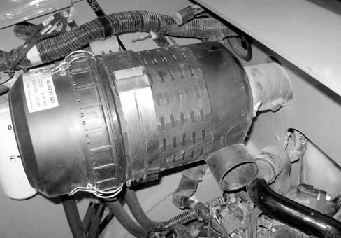
6.If the engine is equipped with a turbo, loosen the clamp (X, Fig. 397) securing air cleaner (Y) to intake tube (Z).
7.Close the engine compartment.
8.Raise the ROPS/FOPS according to “Raising ROPS/FOPS” on page140.
Warning
Secure the ROPS/FOPS in the tilted position with the tilt support. Do not allow anyone under the ROPS/FOPS if it is not supported in the raised position.
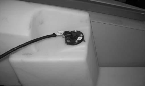
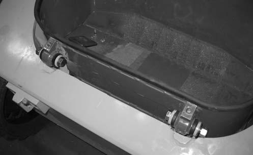
9.Remove hardware (X, Fig. 398) securing foot tub (U). Lift foot tub (U) and disconnect electrical connector from the foot throttle. Remove foot tub (U). Retain hardware (X) for installation.
10.Drain the fuel tank using suction.
Warning
Diesel fuel is flammable. Keep the machine away from open flames. Do not smoke or have any spark- or flame-producing equipment or materials in the area when working around the fuel system. Wipe up spills immediately. NEVER use a shop rag to catch fuel draining fuel. Vapors from the rag are flammable and explosive. Work only in a well ventilated area. Failure to follow these instructions can cause fire and result in injury or death.
11.Disconnect fuel sender electrical connector (A, Fig. 398) from fuel sender (B).
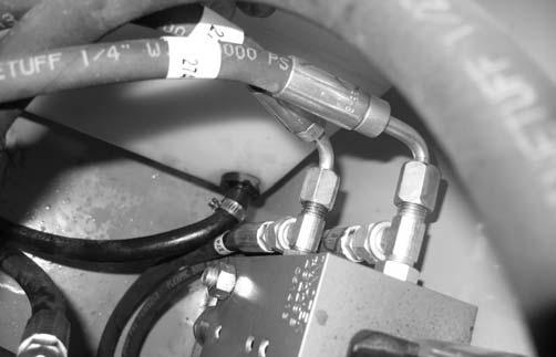
13.Tip the fuel tank to allow access to the fuel line (D, Fig. 401) exiting the front of the fuel tank. Loosen the clamp securing fuel line (D). Remove and cap fuel line (D).
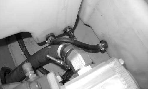
12.Have an assitant lift the fuel tank slightly and loosen the clamp securing fuel line (C, Fig. 400) exiting the rear section of the fuel tank. Remove and cap fuel line (C).
14.Support the ROPS/FOPS in the raised position using an overhead hoist.
Warning
Secure the ROPS/FOPS in the tilted position. Do not allow anyone under the ROPS/FOPS if it is not supported in the raised position.


