1 minute read
Models 1750RT/2100RT Tier 4 Engine Removal/Installation


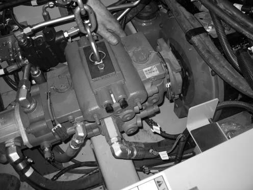
IMPORTANT: Refer to the labeling for tube positioning (O, Fig. 378) made during engine removal for proper tube installation locations.
33.Connect tubes (O) to the control valve tighten securely.
37.Attach a lift bracket (X, Fig. 380) to the top of the hydraulic pump, to allow lifting the hydraulic pump using a hoist (Y).
NOTE: Lift bracket (X) needs to be fabricated. Threading for mounting bracket holes for lift bracket (X) is M12-1.75.
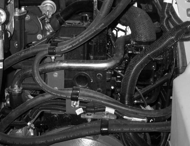
34.Secure hose/cable clamp bracket (M, Fig. 379) against the engine block with 3 fasteners removed during engine removal.
35.Secure the battery ground cable to the engine block using screw (N). Tighten securely.
36.Secure hose/cable clamp bracket (O) to the engine block using screws (L). Tighten securely.
38.Lift the hydraulic pump slightly, and pull the pump rearward, meshing the splined driveshaft on the pump into the engine. Pull the pump tight against the engine
NOTE: A come-along hand winch may be required to pull the hydraulic pump rearward against the engine.