1 minute read
Models 1750RT/2100RT Tier 4 Engine Removal/Installation


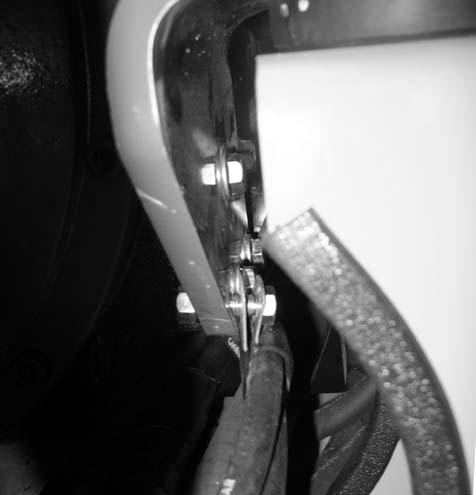
26.Remove screws (H, Fig. 322) and flat washers (I) from both front motor mounts. Discard screws (H), but retain washers for installation.
NOTE: Screws (H) should be replaced for installation. Refer to the parts manual for ordering information.
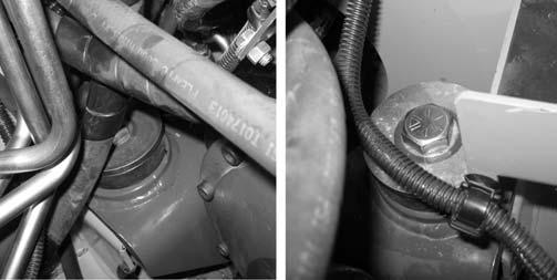
27.Remove clamp (K, Fig. 323) securing fuel line (L) to the left front engine mount. Retain clamp (K) and fasteners for installation.
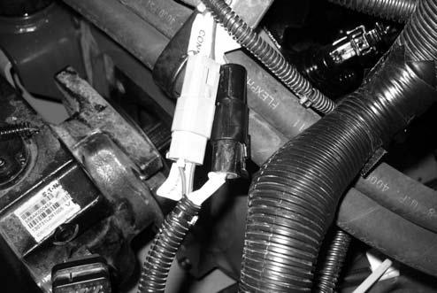
29.Disconnect “C182” engine connector (F, Fig. 325) and “C181” starter solenoid connector (G).
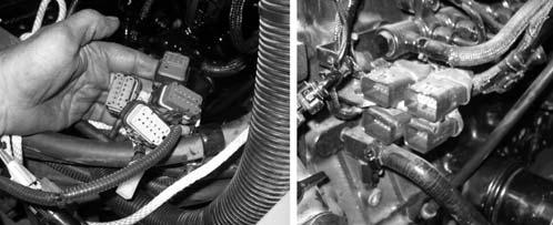
NOTE: Label electrical connections (J, Fig. 324) and note their locations to ensure correct installation.
28.Disconnect electrical connections (J) from the left front of the engine.
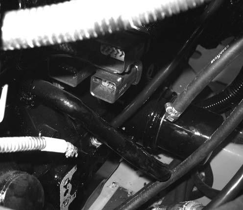
30.Disconnect oil pressure ring connector (H, Fig. 326) from oil sender (I).


