1 minute read
Models 1750RT/2100RT Tier 4 Engine Removal/Installation


NOTE: ROPS/FOPS prop bar (Y) needs to be removed to allow the ROPS/FOPS to be tilted far enough to allow for fuel tank removal.
14.Tilt the fuel tank up and remove it from the machine.
15.Postion ROPS/FOPS tilt prop bar (Y, Fig. 316) back into the bracket on the bottom of the ROPS/FOPS and replace hardware/components removed during step 13. Secure ROPS/FOPS prop bar (Y) with nut (X).
IMPORTANT: Replace the tilt prop bar components to match their positions prior to removal. Refer to Fig. 316.
Warning
Secure the ROPS/FOPS in the tilted position using the tilt prop bar. Do not allow anyone under the ROPS/FOPS if it is not supported in the raised position.
16.The overhead hoist support used for keeping the ROPS/FOPS in the raised position can now be removed.
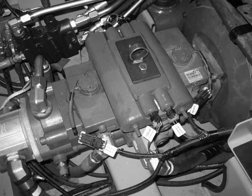
IMPORTANT: Label all electrical connectors (R, Fig. 317) and note their locations to ensure correct installation.
17.Unplug electrical connections (R) and set wire harness/connectors to the side to prevent them from getting damaged.
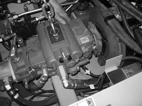
18.Remove fasteners (S) securing the hydraulic pump to the engine. Discard 1/2” capscrews, but retain washers for installation.
NOTE: 1/2” capscrews (S) should be replaced for installation. Refer to the parts manual for ordering information.
19.Attach a lift bracket (X, Fig. 318) to the top of the hydraulic pump, to allow lifting the hydraulic pump using a hoist (Y).
NOTE: Lift bracket (X) needs to be fabricated. Threading for mounting bracket holes for lift bracket (X) is M12-1.75.


