1 minute read
1750RT/2100RT interim Tier 4 Engine Removal/Installation


NOTE: Threading for mounting bracket holes for lift bracket (X) is M12-1.75.
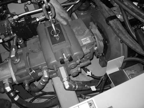
24.Lift the hydraulic pump slightly, and pull the pump forward until it clears the engine.
NOTE: A come-along hand winch may be required to pull the hydraulic pump forward.
25.Remove screws (E, Fig. 408) and hose/cable clamps (F) from the engine block.
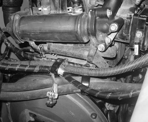
27.Remove cable ties (W).
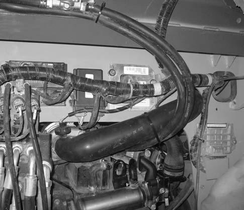
28.If the engine is equipped with a turbo: a.Remove cable tie (A, Fig. 410). b.Remove cable tie (A). c.Pull heater supply (V) and return (U) hoses out of the engine compartment. d.Disconnect wiring connector (B) from sensor (C). e.Loosen clamp (D), and remove intake tube (Z). Cover the intake opening on the turbocharger to prevent debris from entering the turbocharger.
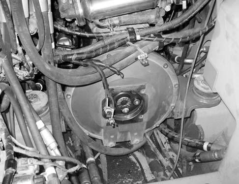
26.Remove screws (G, Fig. 409) and large flat washers (H) from both front motor mounts. Discard screws (G), but retain washers for installation.
NOTE: Screws (G) should be replaced for installation. Refer to the parts manual for ordering information.