1 minute read
1750RT/2100RT interim Tier 4 Engine Removal/Installation


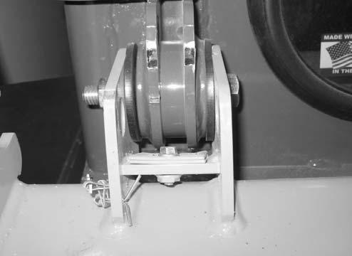
47.Model 1750RT (Serial Numbers 30870 and before), and Model 2100RT (Serial Numbers 40420 and before) a.Remove bolt (F, Fig. 468) securing ROPS/ FOPS tilt stop plates (H). Remove tilt stop plates (H). Retain tilt stop plates (H) and bolt (F) for reassembly.
Model 1750RT (Serial Numbers 30870 and Before) Model 2100RT (Serial Numbers 40420 and Before)
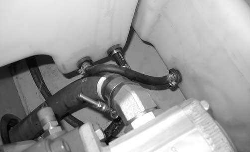
50.Have an assitant lift the fuel tank slightly to allow access to the rear fuel line fitting and connect fuel line (C, Fig. 470). Secure fuel line (C) with hose clamp. Tighten clamp securely.
NOTE: Tilt stop plates (H) need to be removed to allow the ROPS/FOPS to be tilted far enough to allow for fuel tank installation.
48.Tilt/position the fuel tank back into place inside the machine.
49.Tip the fuel tank to allow access to the front fuel line fitting and connect fuel line (D, Fig. 469). Secure fuel line (D) with hose clamp. Tighten clamp securely.
51.Lower/position fuel tank into place properly against the bottom of the chassis.
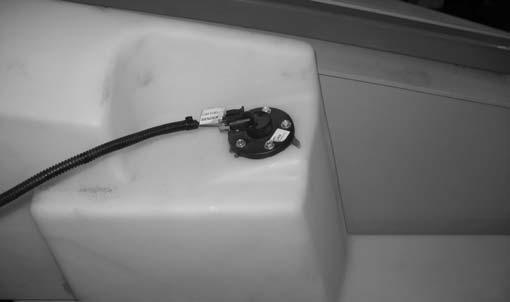
52.Connect fuel sender electrical connector (A, Fig. 471), labeled “C60 FUEL SENDER”, to fuel sender (B).


