15 minute read
Controls


NOTE: Error codes remain displayed even if they are no longer active. To determine if an error is still active, press and release the multi-function button several times to refresh the display. If the error is no longer active, the code(s) will not reappear in the screen rotation.
Configuration Screens
Table 25: Configuration Screens
ItemAccess/Description
Configuration Selection Screens
Configuration Selection Screens
To access these screens, press and hold interface button (Z, Fig. 8) for 5 seconds. Press and release interface button (Z, Fig. 8) to move selection caret (A) down through the configuration selections. Press and hold interface button for 5 seconds to go to the configuration screen selected by selection caret (A).
To exit the configuration selection screens, move selection caret (A) to the “EXIT” option and press and hold interface button for 5 seconds.
DPF Regeneration Configuration Selection Screen
Models 1750RT and 2100RT with Tier 4 Engines)
To access this screen, press and hold interface button (Z, Fig. 8) for 3 seconds. Press and release interface button (Z, Fig. 8) to move selection caret (A) down through the selections to the DPF regeneration configuration selection. Press and hold interface button for 5 seconds to go to the DPF regeneration configuration screen.
To exit the configuration selection screen, move selection caret (A) to the “EXIT” option and press and hold interface button for 5 seconds.
Configuration Screens
Control Sensitivity Configuration Screen
To change joystick control sensitivity, press and release interface button (Z, Fig. 8) to scroll through selections and change control sensitivity. With the caret closer to the symbol, joystick control becomes increasingly aggressive and immediate; with the caret closer to the symbol, joystick control becomes less aggressive and more relaxed.
Control sensitivity configuration changes are saved when exiting this screen. To exit this screen, press and hold interface button for 5 seconds.
Travel Speed Limit Configuration Screen (Option)
This screen displays only on machines equipped with the speed limit option. Press and release interface button (Z, Fig. 8) to choose between H-L (high/low) or speed limit travel drive modes. See “Travel Speed Range Selection” on page66 for more information about the travel speed limit option.
Vehicle speed limit configuration changes are saved when exiting this screen. To exit this screen, press and hold interface button for 5 seconds.
Table 25: Configuration Screens
Control Joystick ISO/D-H Pattern Selection Screen (Option)
This screen displays only on machines equipped with the D-H control pattern option. Press and release interface button (Z, Fig. 8) to choose between ISO or D-H joystick control options. See “Control Joysticks” on page57 for more information about the ISO and D-H control options.
Control joystick pattern configuration changes are saved when exiting this screen. To exit this screen, press and hold interface button for 5 seconds.
Coolant Temperature °F/°C Units Selection Screen
Press and release interface button (Z, Fig. 8) to choose between coolant temperature display options (°F/°C).
Coolant temperature units configuration changes are saved when exiting this screen. To exit this screen, press and hold interface button for 5 seconds.
Display Screen Contrast Configuration Screen
Press and release interface button (Z, Fig. 8) to adjust the screen contrast. Screen contrast changes are saved when exiting this screen. To exit this screen, press and hold interface button for 5 seconds.
Display Screen Font Size Configuration Screen
Press and release interface button (Z, Fig. 8) to adjust the font size. Font size changes are saved when exiting this screen. To exit this screen, press and hold interface button for 5 seconds.
Night/Day Display Change Configuration Screen
To maximize display visibility, the display changes between a black-on-white display and a white-on-black display, depending upon the intensity of ambient light. The set point where this change occurs can be adjusted using this screen.
Press and release interface button (Z, Fig. 8) to adjust the night/day display change set point. When the caret is closer to the symbol, the display changes in brighter ambient light; when it is closer to the symbol, the display changes in lower ambient light.
Night/day display configuration changes are saved when exiting this screen. To exit this screen, press and hold interface button for 5 seconds.
Table 25: Configuration Screens
ItemAccess/Description
Straight Tracking Adjust Screen
Models 1750RT (Serial Numbers 30871 and Up), 2100RT (Serial Numbers 40421 and Up) and 2500RT (All Serial Numbers)
This screen sets the drive to track straight in forward and reverse directions.
See “Straight Tracking Adjust” on page61 for more information about the straight tracking adjust feature.
DPF Regeneration Configuration Screen
Models 1750RT and 2100RT with Tier 4 Engines)
This screen:
•Displays DPF regeneration allow / inhibit status
•Allows DPF reset regeneration to be inhibited
•Initiates a forced DPF stationary regeneration
See “Diesel Particulate Filter (DPF) Regeneration Procedures” on page81 for more information.
Audible Alerts
The multi-function display screens also emits audible alerts (buzzer) under the following conditions:
Table 26: Audible Alerts
ItemDescription
4 Hz alarm – 5 secondsWhen ignition is activated.
2 Hz alarm Engine temperature too high. Engine oil pressure too low. Hydraulic oil temperature too high Low battery / charging fault.
Control Joysticks
The control joystick forward and back, and right to left tilting movements perform the following functions:
•Track drive control
•Lift arm raise/lower and attachment tilt
Buttons and switches on the control joysticks perform the following functions:
•High/low speed mode control
•Lift arm float activation/deactivation
•HydraglideTM activation/deactivation (optional)
•Horn operation
•Auxiliary hydraulics flow control (momentary and continuous)
Joystick Tilt Function ISO/D-H Control Patterns
Control joystick functions are factory-configured to follow ISO-pattern controls. An optional additional D-H control pattern factory option is available.
Machines equipped with the optional D-H control pattern can switch between ISO and D-H control pattern functionality using the multi-function display control joystick ISO/D-H pattern selection screen.
Activating D-H Control Pattern Option
NOTE: Machines not equipped with the optional D-H control pattern will not display the control joystick ISO/D-H pattern selection screen.
1.Hold down the interface button (Z, Fig 9) on the multi-function display until the configuration selection screen (Fig 10) displays.
2.Press and release the interface button until the selection caret points to the “ISO/D-H” selection (Y, Fig 10). Press and hold the interface button until the ISO/D-H Control Pattern Selection screen (Fig 11) displays.
3.Press and release the interface button until the selection caret points to the “D-H” selection (X, Fig 11). Press and hold the interface button until the configuration selection screen (Fig 12) displays.
Left Joystick Functions
4.Press and release the interface button until the selection caret points to the “EXIT” selection (W, Fig 12). Press and hold the interface button until the home status screen displays. The D-H control pattern option is now activated.
Deactivating D-H Control Pattern Option
D-H control pattern option deactivation is identical to activation, with the exception of moving the selection caret to the “ISO” selection (V, Fig 11).
Table 27: Left Control Joystick Functions Joystick
A
B
C
D Right
D-H Control Pattern (Optional) drive – right turn1
E ForwardTrack drive – left track forward
F RearwardTrack drive – left track reverse
G LeftLift arm – up
H RightLift arm – down
1.Tilting joystick directly left or right results in spin turns; tilting joystick diagonally results in more gradual turns.
Right Joystick Functions
Joystick Buttons/Switch Functions
Joystick DirectionFunction
ISO Control Pattern
A ForwardLift arm – down
B RearwardLift arm – up
C LeftAttachment tilt – tilt back
D RightAttachment tilt – tilt forward
D-H Control Pattern (Optional)
E ForwardTrack drive – right track forward
F
RearwardTrack drive – right track reverse
G LeftAttachment tilt – tilt back
H RightAttachment tilt – tilt forward
ButtonFunction
Left Joystick Buttons
A
High/low drive speed selection (See “Travel Speed Range Selection” on page66)
B Horn
Right Joystick Buttons/Switch
C Lift arm float (See “Lift Arm Float” on page99)
HydraglideTM (See “Hydraglide™ Button (Option)” on page69 and “Hydraglide™ Ride Control System (Option)” on page100)
Auxiliary hydraulics flow (See “Powering Attachments with Hydraulic Function” on page107)
Auxiliary hydraulics continuous flow lock (See “Auxiliary Hydraulics Operation” on page108)
Auxiliary hydraulics continuous flow will remain locked with the restraint bars in the raised position with the operator seat not occupied.
Joystick Control Sensitivity
The sensitivity of the ISO drive controls can be configured to be more or less aggressive/immediate. Five levels of control sensitivity are available.
Configuring Control Sensitivity
1.Hold down the interface button (Z, Fig 16) on the multi-function display until the configuration selection screen (Fig 17) displays.
2.Press and release the interface button until the selection caret points to the / control sensitivity selection (Y, Fig 17). Press and hold the interface button until the Control Sensitivity Selection screen (Fig 18) displays.
V More Aggressive/ Immediate
Less Aggressive/ More Relaxed
4.Press and release the interface button until the selection caret points to the “EXIT” selection (W, Fig 35).
3.Press and release the interface button as required to select the desired level of control sensitivity (Fig 18). Five levels of control sensitivity are available.
Move the selection caret toward the top of the screen (V []) for more aggressive and immediate control sensitivity; move the selection caret toward the bottom of the screen (X []) for less aggressive and more relaxed control sensitivity.
Press and hold the interface button for 5 seconds to save control sensitivity configuration changes.
5.Press and hold the interface button until the home status screen displays. The currently selected control sensitivity is now activated.
Straight Tracking Adjust
Models 1750RT (Serial Numbers 30871 and Up), 2100RT (Serial Numbers 40421 and Up) and 2500RT (All Serial Numbers) straight in forward and reverse directions.
NOTE: Tracking adjustment is dependent upon drive motor maximum speed settings on models 1750RT (serial numbers 30870 and before) and 2100RT (serial numbers 40420 and before). On these machines, drive motor maximum speed adjustments are performed at the hydraulic pump. See “Drive Motor High Speed Adjustment” on page268.
1.Move the machine to an open area away from bystanders.
Warning
Always move the machine to an open area, away from bystanders, before using the tracking adjust feature. The travel drive must be operated for several seconds in the forward and reverse directions during the tracking adjust procedure. Allow sufficient room away from bystanders, buildings, machinery and other objects.
2.Apply the parking brake.
3.If the controls are set to the option DH control pattern, set the controls to ISO pattern by deactivating the DH control pattern option. See “Deactivating D-H Control Pattern Option” on page58.
NOTE: The straight tracking adjust feature can only be set while in ISO mode. Adjustments cannot be made while in DH mode.
Once straight tracking is adjusted, the setting applies when operating in either ISO or DH modes, and also top speed limit modes.
4.Press and hold the interface button (Z, Fig.20) on the display until the configuration selection screen (Fig.21) displays.
5.Press and release the interface button until the selection caret points to the straight tracking adjust selection (T, Fig 21).
6.Press and hold the interface button until the straight tracking adjust screen (U, Fig.22) displays.
NOTE: Once this symbol is displayed, the tracking adjustment reverts to the original factory setting. The new adjustment will therefore be set relative to this original setting, not relative to where it was set previously.
7.Release the parking brake. See “Disengage Parking Brake” on page78.
8.To set forward/reverse straight tracking:
• Forward direction – While holding left joystick (A, Fig. 23) fully forward, move the joystick either slightly left or right as required until the machine is tracking straight. With the joystick held in this position, press and hold interface button (Z, Fig.20) until the straight tracking screen (U, Fig.22) is dismissed.
NOTE: The joystick needs to be moved fully forward when adjusting straight tracking or the setting will not be changed.
• Reverse direction – While holding the left joystick (B, Fig. 23) fully back, move the joystick either slightly left or right as required until the machine is tracking straight. With the joystick held in this position, press and hold the interface button (Z, Fig.20) until the straight tracking screen (U, Fig.22) is dismissed.
NOTE: The joystick needs to be moved fully back when adjusting straight tracking or the setting will not be changed.
9.Press and release the interface button until the selection caret points to the “EXIT” selection (W, Fig 24). Press and hold the interface button until the home status screen displays.
10.Operate the machine and verify that it tracks straight when the left joystick is pushed straight forward or back. Repeat this procedure if necessary.
NOTE: Once straight tracking is adjusted, the setting applies when operating in either ISO or DH modes, and also top speed limit modes.
Parking Brake/Work Hydraulics Lock-out
The parking brake is automatically applied whenever either of the safety bars/arm rests are in the raised position (B, Fig 25).
NOTE: Raising the safety bars/arm rests also locks out work hydraulic functions.
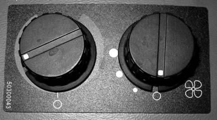
Cab Heat and Air Conditioning (Option)
Controls for cab heat and air conditioning are located on the left control panel. The same controls are used to control both heating and air conditioning.
Control the heat/air conditioning fan using knob (A). Turning the knob clockwise increases fan speed; counter-clockwise decreases fan speed. On early machines, all the way counter-clockwise turns heat/air conditioning off.
Control the heat/air conditioning output temperature using knob (B). Turn the knob clockwise for warmer temperature; counter-clockwise for cooler temperature.
On later machines, rocker switch (C) turns the air conditioning compressor on/off. Press the top of switch (C) to turn the compressor on; press the bottom to turn the compressor off.
NOTE: The parking brake is also applied whenever the operator leaves the seat, or if the cab door is opened.
IMPORTANT: The engine cannot be started with the safety bars/arm rests in the raised position, if the operator is not in the operator’s seat, or if the cab door is not closed.
Later Machines
Early Machines
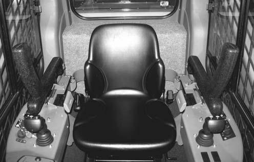
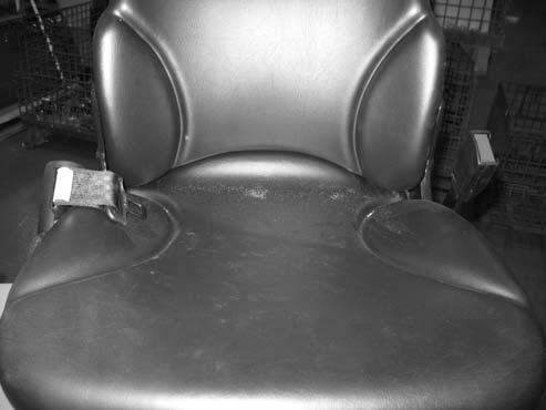
Operator’s Seat
The operator’s seat has adjustments for:
•Forward and back horizontal position (G, Fig. 27).
•Up and down vertical height/weight suspension (E).
Warning
Never adjust the seat when the machine is in operation. Adjust the seat only when the machine is stopped and the arm rests/safety bars are in the raised position.
After adjustments, make sure the seat adjustment levers are fully engaged before using the machine.
Seat Forward and Back Horizontal Adjustment
While sitting in the operator’s seat, pull up on handle (G, Fig. 27). Move the seat and control lever base forward or back as desired. Release bar (G) when the seat is in the desired position. Make sure the seat is locked in position after adjusting.
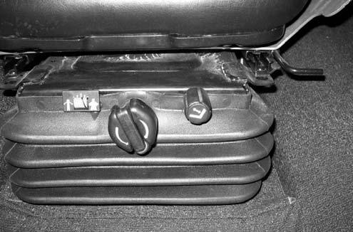
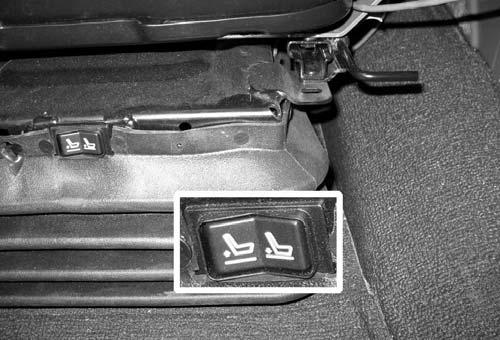
Seat Height Vertical Height/Weight Suspension Adjustment
Air Suspension
While sitting in the operator’s seat, press the left/ right side of toggle switch (H) as necessary to compensate for the drivers weight and preferred seat suspension stiffness. Toggle switch (H) to the left (K) to reduce support; toggle switch to the right (J) to increase support.
Mechanical Suspension
While sitting in the operator’s seat, turn knob (E, Fig. 27) as necessary to center the black line on the yellow background in indicator (F).
Seat Belt
Warning
ALWAYS fasten the seat belt securely and properly. Never operate the machine without the seat belt fastened around the operator.
Keep the seat belt clean; dirt can impair seat belt operation. Check seat belt condition regularly and have damaged or worn belts immediately repaired by an authorized workshop.
After an accident, the seat belt strap is stretched and must be replaced with a new strap installed by an authorized workshop.
Make sure the seat belt is not twisted when it is fastened, and that it is fastened over the hips and not the stomach.
Fasten the seat belt tightly and securely. Remove hard, edged or fragile objects from your pockets or clothes that might lie between the seat belt and your body.
Fastening/Unfastening the Seat Belt
Fasten the seat belt around your hips and waist and insert tongue (A, Fig 28) into clasp (B) until it clicks securely in place. Slack in the seat belt should automatically retract into seat belt spool (K).
Armrest/Joystick Console Adjustment
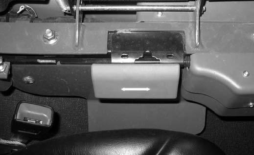
The forward/rearward position of the armrests/ joystick consoles can be adjusted.
To adjust armrest/joystick console position, lift slide lock (Z, Fig 29) and slide armrest/joystick console to the desired position. Release slide lock (Z) to lock the armrest/joystick console in place.
If the seat belt spool does not retract slack in the seat belt, have it serviced immediately. Do not operate the machine until the seat belt is repaired.
Unfasten the seat belt by pressing button (D).
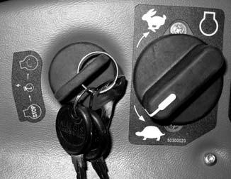
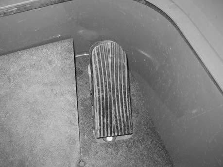
Throttle Controls
Engine throttle controls engine speed, which determines available power.
Engine throttle is controlled with both a knob (I, Fig 30) and a pedal (J).
Travel Controls
Forward, reverse and turning functions are performed using the control joysticks. See “Control Joysticks” on page57.
Travel Speed Range Selection
The machine has 2 travel speed ranges and one changeable speed limit option.
Pressing the speed range select button (K, Fig 31) on the left control joystick toggles between the two speed ranges. Indicator (H) is lit when the highspeed travel range is selected; indicator (H) goes out when low-speed range is selected.
NOTE: Low-speed range is automatically selected when the machine is started.
The throttle knob (I) is the primary throttle control. Generally, the throttle is set with the knob to the desired idle/run position. The pedal can then be used to increase engine speed whenever additional power is required. When the pedal is released, the engine returns to the speed set by the throttle knob.
•Low-speed range:
–Model 1750RT: 0-8.2 kph (0-5.1 mph).
–Models 2100RT/2500RT: 0-8.7 kph (0-5.4 mph).
•High-speed range:
–Model 1750RT: 0-12.1 kph (0-7.5 mph).
–Model 2100RT/2500RT: 0-12.7 kph (0-7.9 mph).
Warning
Reduce speed before shifting from high to low travel speed. Down-shifting from high- to lowspeed drive while traveling at high speed may cause the machine to tip and can cause injury, loss of control and damage to the machine.
2.Press and release the interface button until the selection caret points to the travel speed limit configuration selection (Y, Fig 33). Press and hold the interface button until the Travel Speed Limit Selection screen (Fig 34) displays.
NOTE: Use the low-speed range for loading, unloading, and operations requiring precise speed control. Use the high-speed range for distance traveling.
Travel Speed Limit (Option)
Travel speed limiting allows for fine control over slower travel speeds.
When the travel speed limit option is activated, ten levels of speed limiting can be selected using the high/low speed selector button (K, Fig 36).
NOTE: See “Travel Speed Limit Option Operation” on page68 for details about using the travel speed limit option when it is activated.
Activating Travel Speed Limit Option
NOTE: Machines not equipped with the travel speed limit option will not display the travel speed limit selection screen.
1.Hold down the interface button (Z, Fig 32) on the multi-function display until the configuration selection screen (Fig 33) displays.
3.Press and release the interface button until the selection caret points to the travel speed limit selection (X, Fig 34). Press and hold the interface button until the configuration selection screen (Fig 35) displays.
4.Press and release the interface button until the selection caret points to the “EXIT” selection (W, Fig 35). Press and hold the interface button until the home status screen displays. The travel speed limit option is now activated.
NOTE: The machine reverts to “H-L” travel mode when the engine is shut down.
Deactivating Travel Speed Limit Option
The travel speed limit option is deactivated in two ways:
•Shut down the engine.
•Repeat travel speed limit activation, with the exception of moving the selection caret to the “H-L” selection (V, Fig 34).
Travel Speed Limit Option Operation
When the travel speed limit option is activated, the currently enabled speed limit range is displayed in the top right corner of the multi-function display screen (L, Fig 36).
Pressing the speed range selection button when the travel speed limit option is activated changes the speed limit range. Ten speed limit ranges are available and limit the travel speed to the following ranges when selected:
Table
Lift Arm Float Button WARNING
Make sure the bucket is lowered to the ground before activating the lift arm float. Activating float with an attachment raised will cause it to fall, which can cause severe injury or death.
Lift arm float is activated by lowering the attachment to the ground and using button (A, Fig. 37) on the right joystick. Press button (A) to activate float; press and hold button (A) for 5 seconds to engage continuous float activation. Press button (A) and quickly release to deactivate float.
NOTE: Indicator on the multi-function display is lit whenever float is activated.
Hydraglide™ Button (Option)
Hydraglide™ cushions lift arm loads during transport. It provides a smoother ride over uneven surfaces.
IMPORTANT: Hydraglide™ is automatically deactivated when the machine is shut off.
On the right joystick, press switch (H, Fig 38) to toggle Hydraglide™ on/off.
NOTE: Indicator on the multi-function display is lit whenever Hydraglide™ is activated.
For lift arm float operation information see “Lift Arm Float” on page99.
For Hydraglide™ operation information see “Hydraglide™ Ride Control System (Option)” on page100.
Work Lights
The switches for the work lights are located on the right console.
Work Lights
Warning
Switch off the work lights when traveling on public roads. Work lights can dazzle motorists and cause accidents.
The front and back work lights operate using the same 3-position switch (Y, Fig 39).
Set switch (Y) to the middle position (V) to turn on the front work lights.
Set switch (Y) to the top (Z) position to turn both the front and back work lights on.
Set switch (Y) to the bottom (X) position to turn the work lights off.
NOTE: Indicator (W) is on when the works lights are activated.
Battery Disconnect Switch (Option)
Before the engine can be started, the battery disconnect switch must be in the “on” position. The battery disconnect switch (A, Fig 40) is located inside the storage box at the back left corner of the machine.
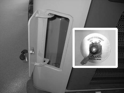
Open the storage box using key (D) supplied with the ignition key.
To disconnect the battery from the electrical system and disable all electrical functions: Turn the switch counter-clockwise to the “OFF” position.
To connect the battery to the electrical system and enable all electrical functions: Turn the switch clockwise to the “ON” position.
Windshield Wipers/Washer
Wiper/Washer Control
Press bottom (A, Fig 41) of wiper switch (C) to activate the wipers. Press and release top (B) of wiper switch (C) to turn the wipers off.
NOTE: Indicator (D) is on when the wipers are activated.
Push and hold top (B) of wiper switch (C) to activate the washer spray. Release the button to stop the spray.
Washer Fluid Reservoir
See “Windshield Washer Reservoir” on page154 for windshield washer reservoir location and filling information.


