1 minute read
1750RT/2100RT interim Tier 4 Engine Removal/Installation


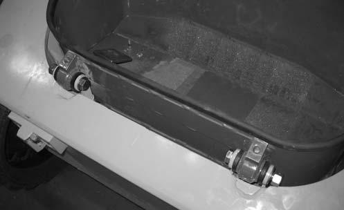
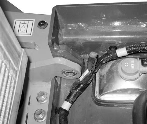
53.Connect electrical connector, labeled “C21 FOOT THROTTLE” to the foot throttle and position foot tub (X, Fig. 472) inside the front chassis. Secure foot tub with hardware (X).
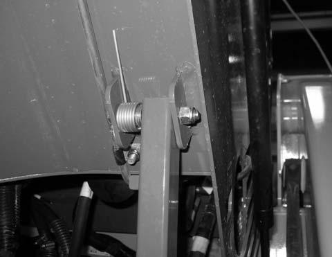
55.Model 1750RT (Serial Numbers 30870 and before), and Model 2100RT (Serial Numbers 40420 and before) a.Replace tilt stop plates (H, Fig. 474) in ROPS/FOPS tilt hinge bracket and secure with bolt (F).
Model 1750RT (Serial Numbers 30870 and Before)
Model 2100RT (Serial Numbers 40420 and Before)
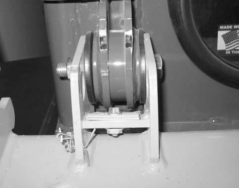
54.Model 1750RT (Serial Numbers 30871 and Up), Model 2100RT (Serial Numbers 40421 and Up) a.Postion ROPS/FOPS tilt prop bar (Y, Fig. 473) into the bracket on the bottom of the ROPS/FOPS and replace hardware/components removed during ROPS/FOPS removal. Secure ROPS/FOPS prop bar (Y) with nut (X).
IMPORTANT: Replace the tilt prop bar components to match their positions prior to removal. Refer to Fig. 473.
Model 1750RT (Serial Numbers 30871 and Up)
Model 2100RT (Serial Numbers 40421 and Up)
NOTE: Tilt stop plates (H) prevent premature wear of the ROPS/FOPS support struts.
56.Remov the overhead hoist support used for keeping the ROPS/FOPS in the raised position.
57.Lower the ROPS/FOPS according to “Lower ROPS/FOPS” on page142.
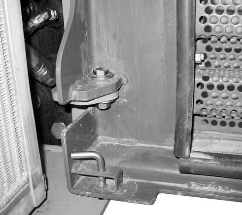
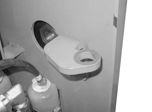
58.Place fiber washer (U, Fig. 475) on the top of upper engine compartment access door hinge mounting bracket (V).

60.Install screw (Y, Fig. 477), 2 flat washers (Z), and nut (A) through the hole in the pin. Tighten securely.
59. Carefully lift engine compartment access door (W, Fig. 476) into position using an appropriate lifting device. Align pins (X) with the holes in mounting bracket (Y) and lower the door until the pins seat in the holes.
61.Install screw (B, Fig. 478), 2 flat washers (C), and nut (D) through the hole in the pin. Tighten securely.