1 minute read
Models 1750RT/2100RT Tier 4 Engine Removal/Installation


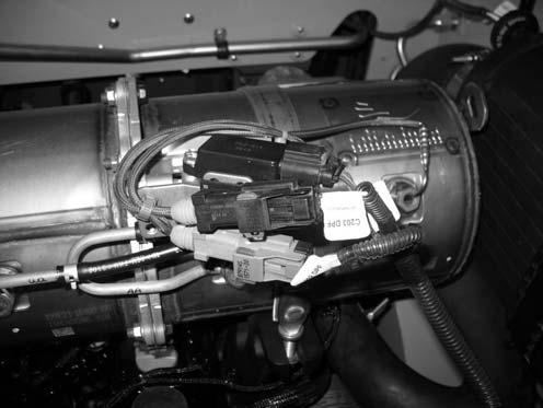
25.Plug DPF electrical connections (A through C, Fig. 371). The connections are labeled as follows:
A.“C180 DPF PRESSURE SENSOR”
B.“C203 DPF MID-TEMP SENSOR”
C.“C202 DPF INLET TEMP SENSOR”
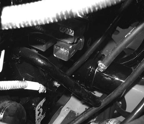
27.Connect oil pressure ring connector (H, Fig. 372) to oil sender (I) at the left front of the engine under the four engine electrical connectors. Tighten securely.
26.Raise the ROPS/FOPS according to “Raising ROPS/FOPS” on page140.
Warning
Always secure the ROPS/FOPS in the tilted position with pins and spring pins. Never allow anyone under the ROPS/FOPS if the tilt securing pins are not in place.
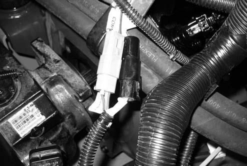
28.Connect “C182” engine connector (F, Fig. 373) and “C181” starter solenoid connector (G).


