1 minute read
Models 1750RT/2100RT Tier 4 Engine Removal/Installation


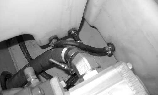
45.Have an assistant lift the fuel tank slightly to allow access to the rear fuel line fitting and connect fuel line (C, Fig. 384). Secure fuel line (C) with hose clamp. Tighten clamp securely.
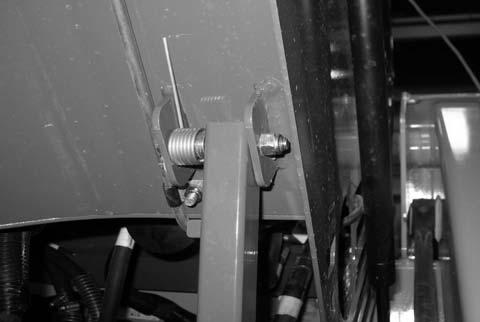
49.Postion ROPS/FOPS tilt prop bar (Y, Fig. 387) back into the bracket on the bottom of the ROPS/FOPS and replace hardware/components removed during step 42. Secure ROPS/FOPS prop bar (Y) with nut (X).
46.Lower/position fuel tank into place properly against the bottom of the chassis.
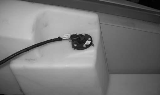
47.Connect fuel sender electrical connector (A, Fig. 385), labeled “C60 FUEL SENDER”, to fuel sender (B).
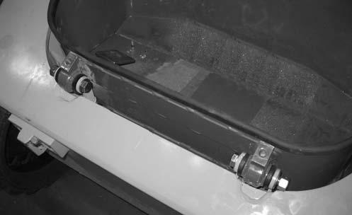
48.Connect electrical connector, labeled “C21 FOOT THROTTLE” to the foot throttle and position foot tub (X, Fig. 386) inside the front chassis. Secure foot tub with hardware (X).
IMPORTANT: Replace the tilt prop bar components to match their positions prior to removal. Refer to Fig. 387.
50.Remove the overhead hoist support used for keeping the ROPS/FOPS in the raised position.
51.Lower the ROPS/FOPS according to “Lower ROPS/FOPS” on page142.