1 minute read
1750RT/2100RT interim Tier 4 Engine Removal/Installation


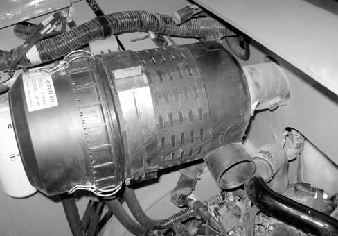
39.If the machine is equipped with a turbo: a.Remove covering protecting the turbo intake from debris and install turbocharger intake tube (G, Fig. 464). Secure intake tube to turbocharger using clamp (H). Tighten securely. b.Connect wiring connector (I) to sensor (J). c.Route heater supply and return hoses (K and L) into the engine compartment. d.Secure heater hoses (K and L) to turbocharger intake tube (G) using a cable tie (M). e.Inside the engine compartment, connect intake tube (G) to air cleaner (Y) and secure with clamp (X). Tighten securely.
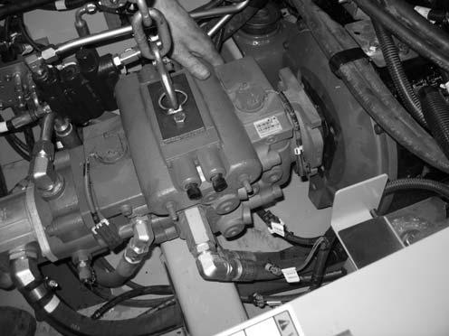
41.Attach a lift bracket (X, Fig. 465) to the top of the hydraulic pump, to allow lifting the hydraulic pump using a hoist (Y).
NOTE: Threading for mounting bracket holes for lift bracket (X) is M12-1.75.
42.Lift the hydraulic pump slightly, and pull the pump rearward, meshing the splined driveshaft in the pump into the engine. Pull the pump tight against the engine.
NOTE: A come-along hand winch may be required to pull the hydraulic pump rearward against the engine.
43.Install new 1/2” capscrews (S) and washers, and secure the hydraulic pump to the engine. Torque capscrews (S) to 101 Nm (75 lb.-ft.)
NOTE: Use new 1/2” capscrews (S) for installation. Refer to the parts manual for ordering information.
40.
44.Plug pump control electrical connections (A through F) into the pump. The connections are labeled as follows:
A.“C6 LH PUMP REV”
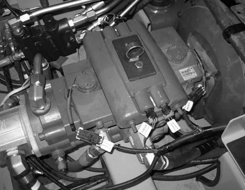
B.“C5 RH PUMP REV”
C.“C7 SWASH PLATE LH”
D.“C20 LH PUMP FWD”
E.“C8 SWASH PLATE RH”
F.“C19 RH PUMP FWD”
45.Support the ROPS/FOPS in the raised position using an overhead hoist.
Warning
Secure the ROPS/FOPS in the tilted position. Do not allow anyone under the ROPS/FOPS if it is not supported in the raised position.
46.Model 1750RT (Serial Numbers 30871 and Up), Model 2100RT (Serial Numbers 40421 and Up) a.Remove nut (X, Fig. 467) securing ROPS/ FOPS prop bar (Y). Remove hardware securing prop bar (Y) to the bracket on the bottom of the ROPS/FOPS, noting the position of the hardware components for reassembly.
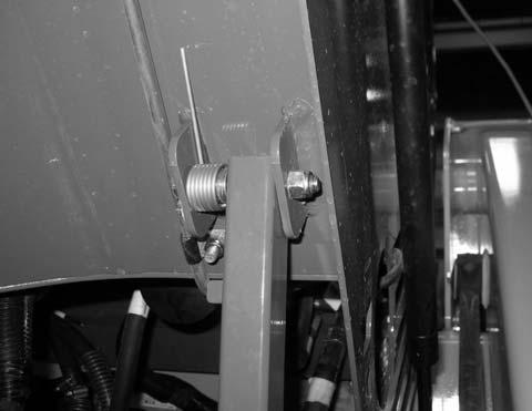
Model 1750RT (Serial Numbers 30871 and Up)
Model 2100RT (Serial Numbers 40421 and Up)
NOTE: ROPS/FOPS prop bar (Y) needs to be removed to allow the ROPS/FOPS to be tilted far enough to allow for fuel tank installation.


