1 minute read
Hydraulic Equipment


Hydrostatic Pump Drive Coupling Removal and Installation
Warning
BEFORE beginning this service procedure, shut down the machine according to “Mandatory Safety Shutdown Procedure” on page8.
Tilt back ROPS/FOPS until lock engages according to “Raising ROPS/FOPS” on page140.
1.Remove the hydrostatic pump according to the pump removal procedure on page270.
IMPORTANT: Use new mounting screws; two [Manitou part # 5028001] (X, Fig. 507), and ten [Manitou part # 50280002], when re-installing the hydrostatic pump.
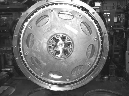
2.Remove socket-head screws securing the flywheel housing (Q) to the engine. Use Loctite™ 242 or equivalent to reinstall. Torque all screws to 45 Nm (33 lb.-ft.).
IMPORTANT: Use new mounting screws [Manitou part # 50302298] when installing the coupler drive plate (R, Fig. 508). Torque 65 Nm (to 48 lb.ft.).
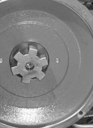
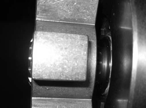
3.Coupler (B) must be installed with 10.03 mm (0.395 in.) between the face of coupler (B) and pump (A).
Yanmar Engines: Install coupler with this side facing engine
Deutz Engines: Install coupler with this side facing pump
IMPORTANT: Do not apply any lubrication or grease to the coupler or flexible coupling plate during installation.
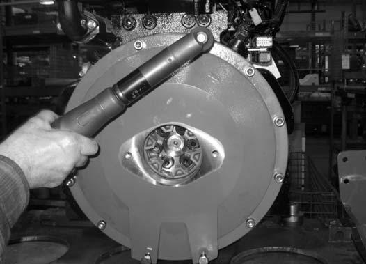
4.When adjusted, torque the set screws to the following value to secure coupler (B) in place on the pump shaft:
•Yanmar Engines: 34 Nm (25 lb.-ft.)
•Deutz Engines: 27 Nm (20 lb.-ft.)
Installation
Install the coupling in reverse order of removal.


