1 minute read
Tier 4 Engine Removal/Installation


Model 1750RT (Serial Numbers 30871 and Up)
Model 2100RT (Serial Numbers 21041 and Up)
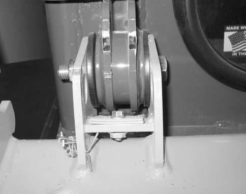
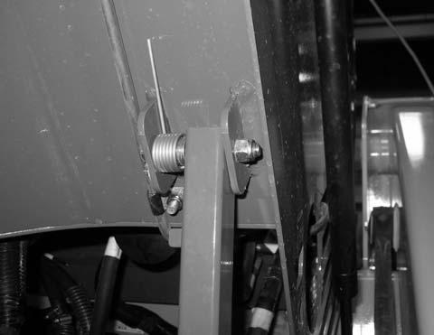
NOTE: Tilt stop plates (H) prevent premature wear of the ROPS/FOPS support struts.
Warning
Secure the ROPS/FOPS in the tilted position using the tilt support. Do not allow anyone under the ROPS/FOPS if it is not supported in the raised position.
20.The overhead hoist support used for keeping the ROPS/FOPS in the raised position can now be removed.
IMPORTANT: Label all electrical connectors (R, Fig. 406) and note their locations to ensure correct installation.
19.Model 1750RT (Serial Numbers 30871 and before), and Model 2100RT (Serial Numbers 21040 and before) a.Replace tilt stop plates (H, Fig. 405) in ROPS/FOPS tilt hinge bracket and secure with bolt (F).
Model 1750RT (Serial Numbers 30870 and Before)
Model 2100RT (Serial Numbers 21040 and Before)
21.Unplug electrical connections (R) and set wire harness/connectors to the side to prevent them from getting damaged.
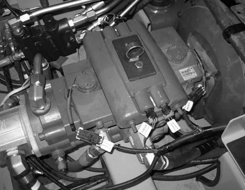
22.Remove fasteners (S) securing the hydraulic pump to the engine. Discard 1/2” capscrews, but retain washers for installation.
NOTE: 1/2” capscrews (S) should be replaced for installation. Refer to the parts manual for ordering information.
23.Attach a lift bracket (X, Fig. 407) to the top of the hydraulic pump, to allow lifting the hydraulic pump using a hoist (Y).